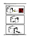
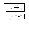
Programming and Operating Concepts
Video Recorder – User Manual 59
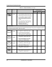
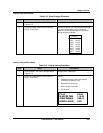
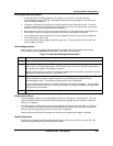
Table 3-9 Function Block Configuration Procedure (continued)
Step Action
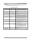
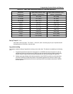
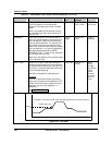
4 Program the function block’s other items as desired. Other items include decimal point positions,
descriptor, tag, and various labels for identifying the function block.
5 Repeat steps 1-4 for all desired function blocks until the instrument is configured.
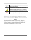
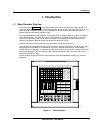
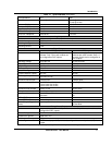
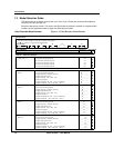
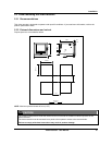
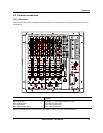
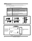
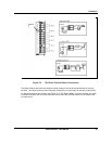
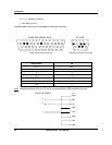
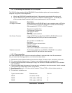
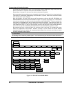
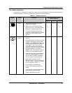
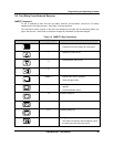
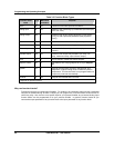
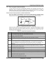
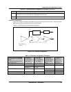
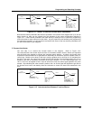
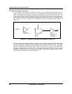
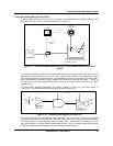
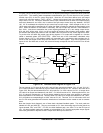
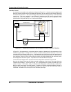
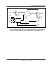
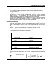
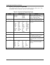
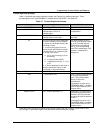
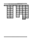
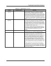
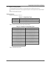
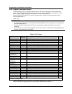
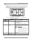
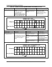
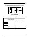
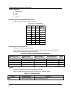
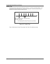
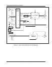
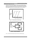
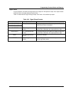
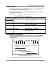
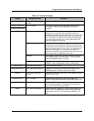
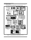
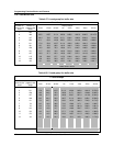
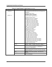
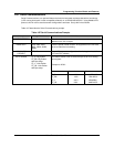
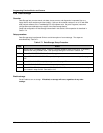
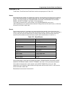
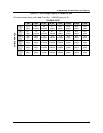
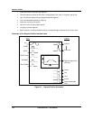
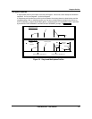
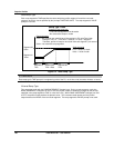
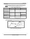
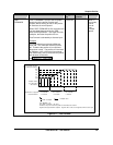
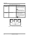
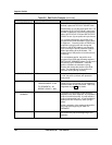
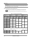
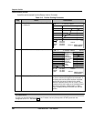
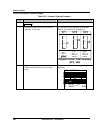
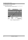
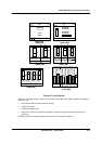
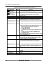
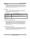
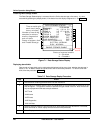
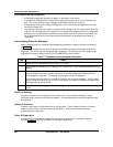
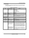
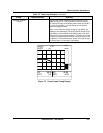
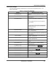
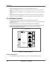
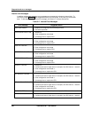
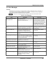
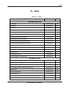
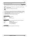
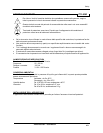
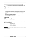
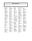
Example configuration
Figure 3-10 shows a simplified configuration using typical function block connections. Note that several
parameters are left out to simplify the drawing and procedure.
Table 3-10 describes how to program these connections.
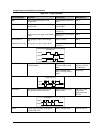
AI 1
LP 1
AO 1
PV
LP1OV
INPUT
SETPOINT#1 =
1500
AL 1 DO 1
AI1OV
INPUT
INPUT
SETPOINT = 500
AL1OS
TYPE = CAT
TYPE = Type J
DO1OS
AO1OV
AO1BC
FEEDBACK
KEY :
FUNCTION BLOCK TYPE
INPUT PARAMETER
FUNCTION BLOCK PARAMETER
PARAMETER CODE
ACTION = HIGH
AI1OV
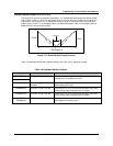
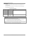
Figure 3-10 Example Configuration
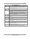
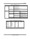
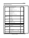
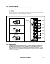
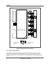
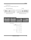
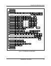
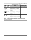
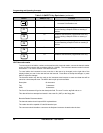
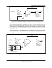
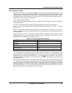
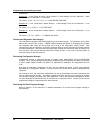
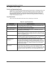
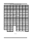
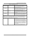
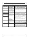
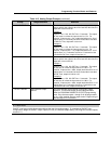
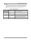
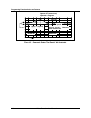
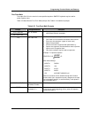
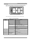
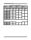
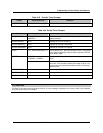
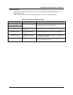
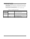
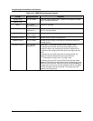
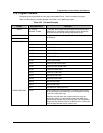
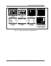
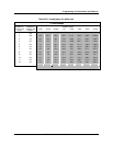
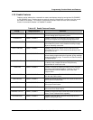
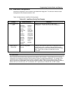
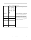
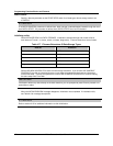
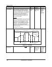
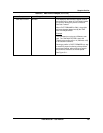
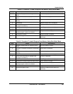
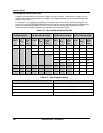
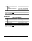
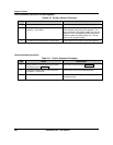
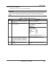
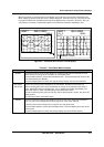
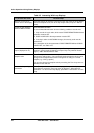
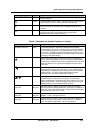
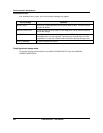
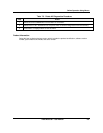
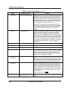
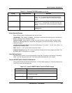
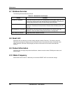
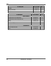
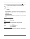
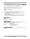
Table 3-10 Example Configuration Procedure
Function block type (Full name
as displayed in the Program
menu)
1. Select this menu item from
the Program menu.
2. Select this
input parameter
from the function
block’s menu...
...and program it
with this output
code. See Section
3.11 for details.
3. Select this
Function block
parameter from the
function block’s
menu...
...and program
it with this
choice. See
Section 3.12
for details.
AI 1 (ANALOG INPUT #1)
-- -- TYPE TYPE J
LP 1 (LOOP #1)
PV AI1 OV SETPOINT#1 1500
FEEDBACK AO1 BC
AL 1 (ALARM #1)
INPUT AI1 OV SETPOINT 500
ACTION HIGH
DO 1 (DISCRETE OUTPUT #1)
INPUT AL1 OS -- --
AO 1 (ANALOG OUTPUT #1)
INPUT LP1 OV TYPE CAT