


Programming Function Blocks and Features
Video Recorder – User Manual 118
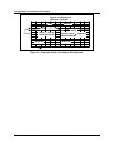
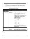
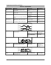
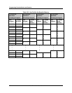
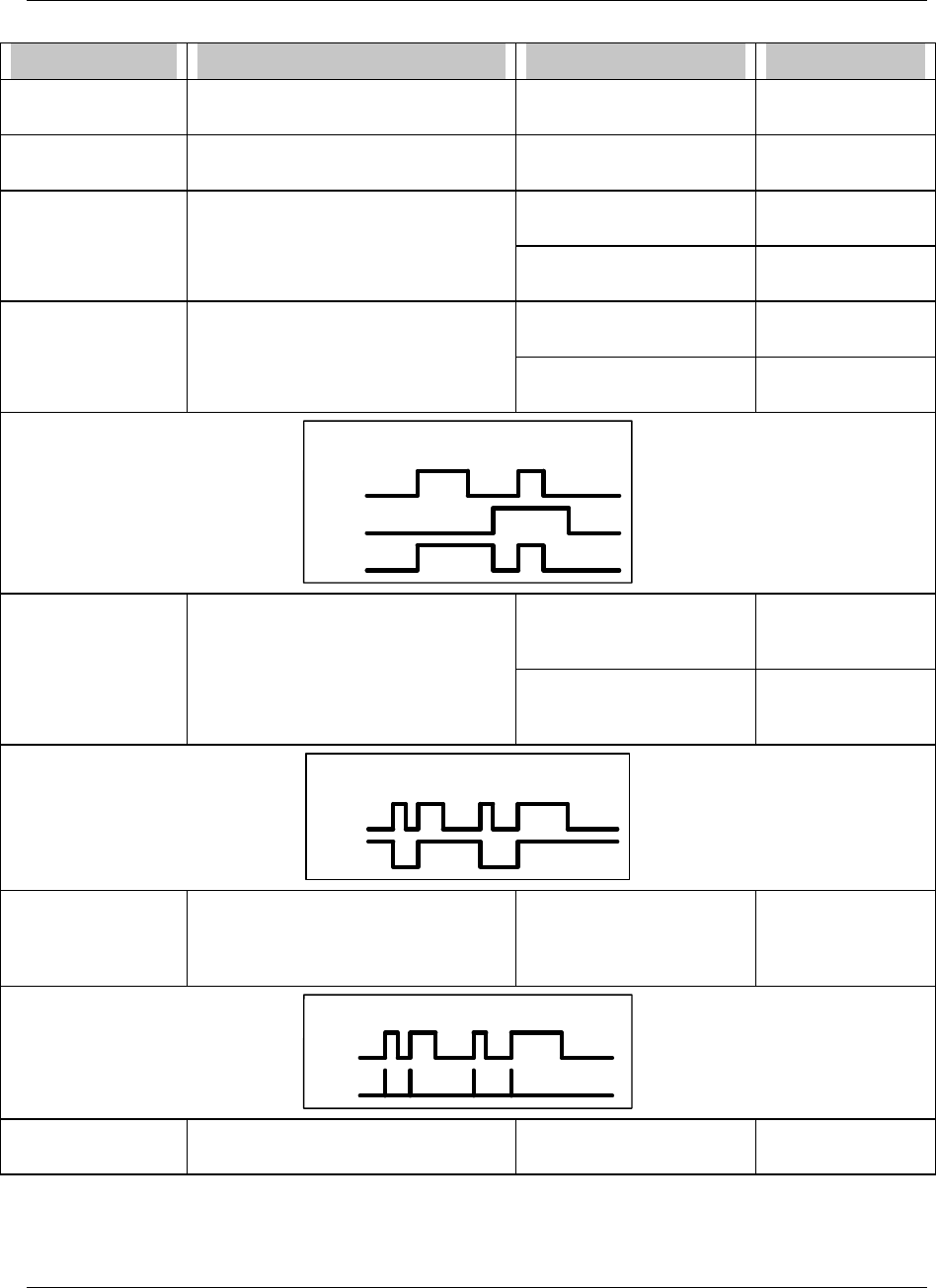
Table 4-26 Logic Operators
For this operator Definition if this is true then Result is
AND If all programmed inputs are ON,
Result is ON.
All programmed inputs are
ON(1)
ON(1)
OR If at least 1 programmed input is ON,
Result is ON.
At least 1 programmed
input is ON(1)
ON(1)
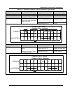
XOR Uses Inputs A and B only. Input A is ON(1) and Input
B is OFF(0).
ON(1)
If one and only one input is ON, Result
is ON.
Input A is OFF(0) and Input
B is ON (1).
ON(1)
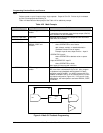
RESET/SET FF Rising edge of Input A turns Result
ON.
Input A is ON(1). ON(1)
(Reset/Set Flip-Flop) Rising edge of Input B resets Result. Input A is OFF(0) and Input
B is ON (1).
OFF(0)
Reset/Set FF
Input A
Input B
Result
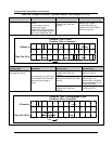
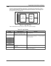
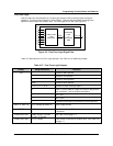
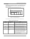
TOGGLE/FF Toggle Flip-Flop. Rising edge of Input
A inverts Result
Input A changes from
OFF(0) to ON(1) (rising
edge)
ON(1) if it was
OFF(0), or OFF(0)
if it was ON(1).
Input A changes from
ON(1) to OFF(0) (falling
edge)
unchanged
Input A
Toggle/Flip-Flop
Result
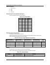
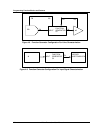
ONE SHOT Rising edge of Input A turns Result
ON for one machine scan cycle.
Input A is ON(1) for any
length of time
ON(1) for 1 scan
cycle of the
instrument, then
OFF(0)
Result
Input A
One Shot
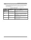
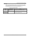
PASS Passes Input A’s state unchanged to
CONDITION TYPE.
Input A changes state same as Input A