


Diagnostic and error messages
Video Recorder – User Manual 254
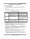
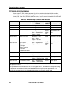
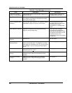
9.2 Loop Error Indicators
When a loop's PV, SP2, or other parameter fails, the loop switches to its default/failsafe condition,
indicated by certain display symbols flashing. To return the loop to its desired condition, correct the
failure. Then, if the loop's LATCHING is NO, the loop will return to normal automatically. If LATCHING
is YES, also perform the action needed to return the loop to normal.
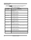
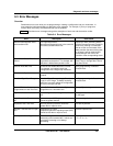
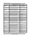
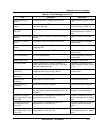
Table 9-3 Abnormal Loop Conditions And Indicators
Desired Condition Abnormal Condition Default condition
(Failsafe)
Flashing
symbols
Action needed
(if LATCHING = YES)
Auto & SP2 SP2 Failure Working SP=SP1 SP2 Select SP1 then SP2
Manual & SP2 SP2 Failure Working SP=SP1 SP2 Select SP1 then SP2
Auto & SP2 SP2 & PV Failure Working SP=SP1
Mode = Suspend Auto*
Output = Failsafe
SP2
AUTO
MAN**
PV
Select SP1 then SP2
Select Manual then
Auto
Manual & SP2 SP2 & PV Failure Working SP = SP1
Mode = Manual
Output = Last value
SP2
PV
Select SP1 then SP2
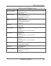
Auto & SP1/SP2
PV Failure or
Force Remote Manual
Failure or
Output Tracking
Failure or
Feedforward Failure
Mode = Suspend Auto*
Output = Failsafe
AUTO
MAN**
PV
Select Manual then
Auto
Manual & SP1/SP2 PV Failure Mode = Manual
Output = Last Value
PV None required
Auto & SP1/SP2 See below***
Mode = Suspend Auto*
Output = Back Calc. Value
AUTO
MAN
None required
Auto & SP1/SP2 Force Remote Manual
Mode = Suspend Auto*
Output = Tracking value
AUTO None required
*Due to the abnormal condition the loop cannot be in Auto and therefore is in a temporary mode which forces
the output as indicated.
**If loop feedback is not connected to an AO, or if loop type is ON/OFF, then MAN will be steady, not flashing.
***Status from a downstream function block indicates that there is no path to final output element. For
example, the secondary control loop of cascade configuration was changed to manual mode.