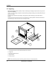
Programming and Operating Concepts
Video Recorder – User Manual 38
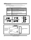
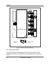
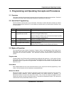
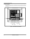
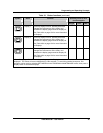
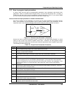
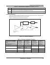
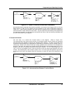
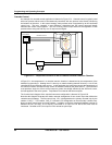
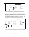
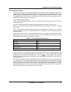
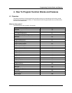
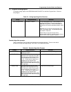
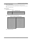
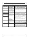
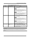
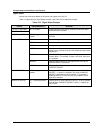
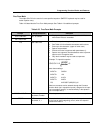
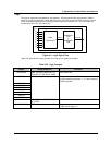
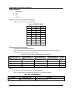
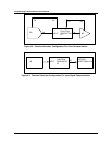
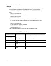
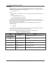
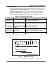
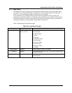
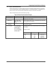
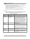
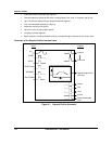
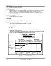
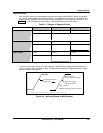
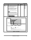
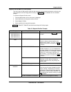
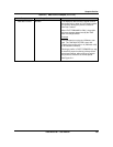
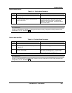
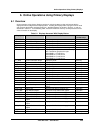
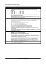
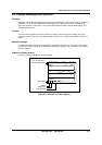
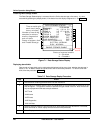
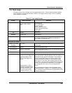
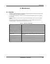
Once within the mode selected in Step 5, scroll through the mode’s MAIN MENU using the Up Arrow and
Down Arrow buttons. Verify each menu choice as indicated in Figure 3-2.
Repeat Steps 3 through 6 for the last of the three mode selections possible.
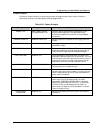
Having completed the preceding exercise, changing the instrument’s mode should now be a simple task.
Furthermore, a fundamental understanding of how the Menu, Up Arrow, Down Arrow, and Enter buttons
work should now be at your fingertips.
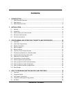
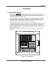
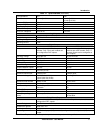
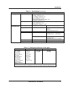
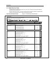
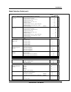
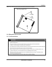
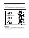
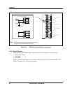
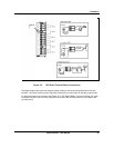
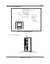
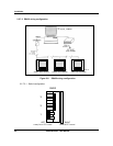
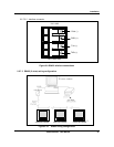
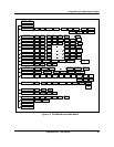
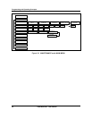
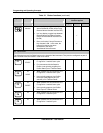
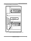
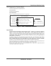
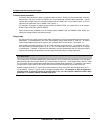
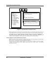
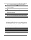
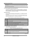
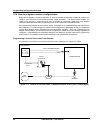
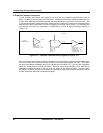
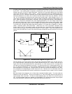
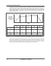
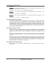
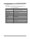
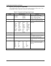
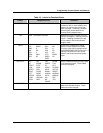
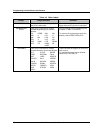
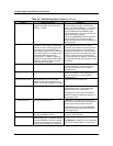
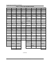
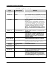
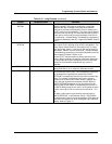
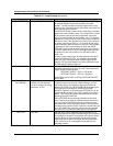
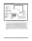
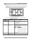
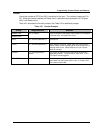
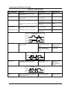
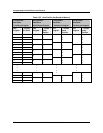
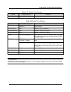
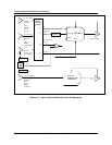
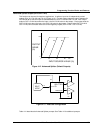
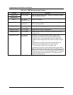
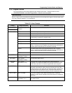
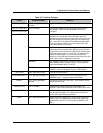
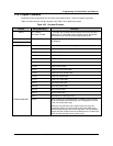
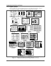
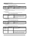
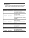
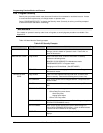
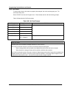
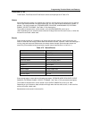
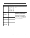
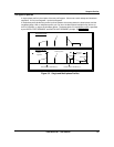
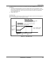
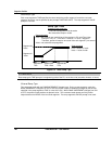
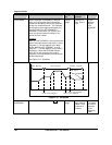
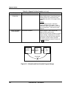
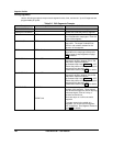
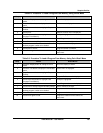
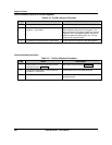
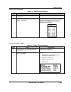
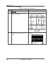
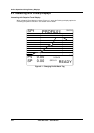
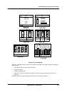
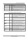
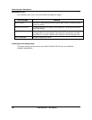
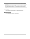
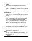
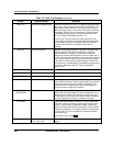
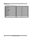
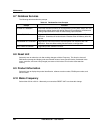
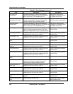
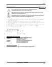
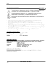
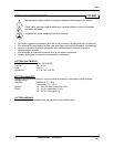
Now use the Menu, Up Arrow, Down Arrow, and Enter buttons to verify the ON LINE, PROGRAM, and
MAINTENANCE mode sub-level menus detailed in Figure 3-3, Figure 3-4 and Figure 3-5. The sub-level
menus shown represent only the first sub-level below each mode’s MAIN MENU. There are several sub-
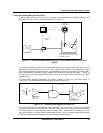
level menus, not indicated here, that run further below each first sub-level. Note that once inside of a
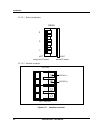
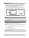
sub-level menu, regardless of how “deep” the level is, a press of the Menu button will return you to the
next highest menu level. In case you get lost within a mode’s sub-level menu, keep pressing the Menu
button until the ON LINE, PROGRAM, or MAINTENANCE mode MAIN MENU appears on screen.
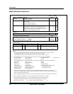
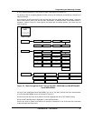
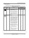
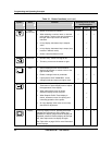
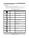
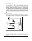
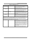
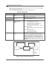
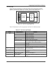
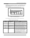
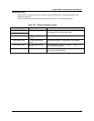
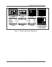
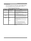
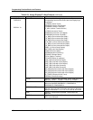
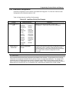
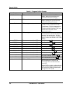
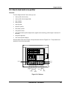
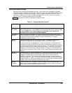
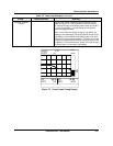
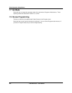
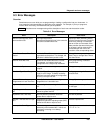
Be advised that Figure 3-2 through Figure 3-5 comprise a basic “road map” for navigating the menus
within the programmer’s three modes. Sections 4 through 8 of this manual will provide detailed
descriptions of each menu choice and complete guides through all the sub-level menus that run below
the levels indicated in these Figures.
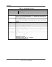
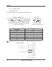
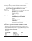
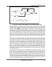
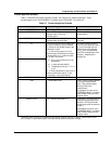
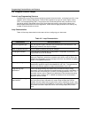
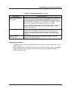
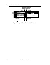
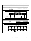
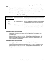
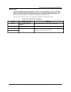
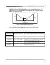
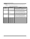
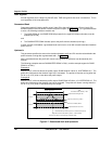
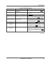
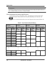
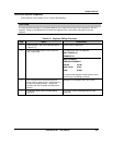
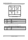
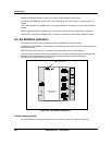
ATTENTION
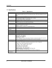
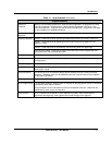
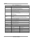
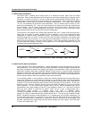
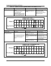
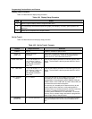
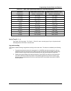
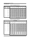
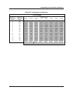
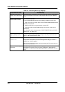
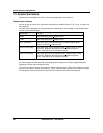
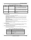
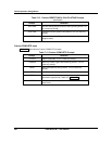
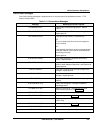
The following menus contain all possible options. Your instrument may not include some items shown here.
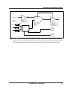
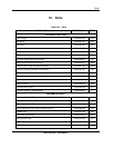
ACCESS SUMMARIES
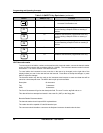
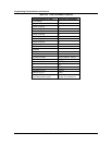
MAIN MENU - ON LINE
DATA ENTRY
DATA STORAGE
DATA STORAGE STATUS
SETPOINT PROFILES
TUNE LOOP
SET ANALOG OUTPUTS
SET MODE ON LINE
DISPLAY ALARM
SUMMARY
DISPLAY ALARM
HISTORY
DISPLAY
DIAGNOSTICS
DISPLAY ALL
ANALOGS
DISPLAY ALL
DISCRETES
DELETE ALL
DIAGNOSTICS
PRODUCT
INFORMATION
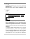
EDIT ALARM
SETPOINTS
EDIT CONSTANTS
FORCE DISCRETE
INPUTS
FORCE DISCRETE
OUTPUTS
ADJUST ANALOG
INPUTS
RESET
TOTALIZERS
ENABLE STORAGE
REPLAY FROM
DISK
INITIALIZE DISK LIST DISK FILES
SET UP NEW
SCHEDULES
REVIEW CURRENT
SCHEDULES
WARNING
LEVEL
BATCH STATEBATCH NUMBER
EDIT PROFILE #1 EDIT PROFILE #2 EDIT PROFILE #3 EDIT PROFILE #4
STORE PROGRAM
TO DISK
STORE PROGRAM
TO MEMORY
LOAD PROGRAM
FROM DISK
LOAD PROGRAM
FROM MEMORY
LOOP #1 LOOP #2 LOOP #3 LOOP #4
OUTPUT #1 OUTPUT #2 OUTPUT #3
OUTPUT #4
RESET ALL
TOTALIZERS
SET ANALOG
OUTPUTS
LOOP #8
. . .
. . .
OUTPUT #8
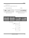
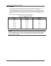
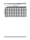
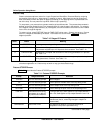
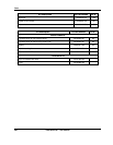
REVIEW PROGRAMMING
CONTROL LOOPS
ANALOG INPUTS ANALOG OUTPUTS DISCRETE INPUTS
DISCRETE OUTPUTS
CALCULATED
VALUES
ALARMSTOTALIZERS
CONSTANTS FEATURES
DISPLAYS
SECURITY
SERIAL COMMUNICATIONS
PROFILES
SCAN RATE
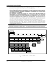
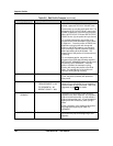
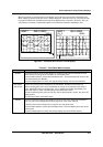
Figure 3-3 ON LINE mode MAIN MENU