


Programming and Operating Concepts
Video Recorder – User Manual 68
Cascade Control
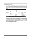
An example of a cascade control application is featured in Figure 3-21. Cascade control is typically used
when two process values must be simultaneously controlled, with one process value directly influencing
the behavior of the other. In this control strategy, each process value is supported by its own dedicated
control loop. The term “cascade” is used because it describes how this control approach literally
attaches both control loops together. This act of linking control loops allows for the regulation of both
process values using one and only one % output control signal.
+~
-
THERMOCOUPLES
INSTRUMENT
PV 200
SP 500
OUT 83.5%
4 TO 20 mA
(CAT)
SCR
AC POWER
SOURCE
ELECTRIC
HEATING
ELEMENT
CHEMICAL
REACTION
VESSEL
OIL
OIL JACKET
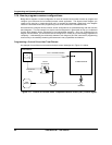
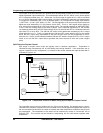
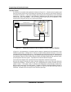
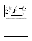
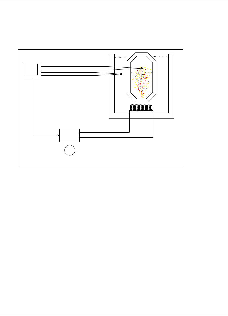
Figure 3-21 Temperature Control Of An Oil Heated Chemical Reaction Chamber
InFigure 3-21, the temperature in a chemical reaction chamber is determined by the temperature of the
heated oil surrounding it. Heating the oil is done by an electric heating element driven by a 4 to 20 mA
controlled SCR and external power source. In this application the instrument controls the temperature of
the chemical reaction chamber through control of the heat emitted by the jacket tank oil. The instrument
must provide a single 4 to 20 mA control output to govern the voltage switched by the SCR and, hence,
the heat applied to the entire system. Temperature is monitored with thermocouples.
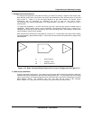
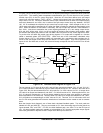
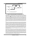
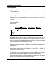
The function block diagram of the required instrument configuration is featured in Figure 3-22
Note that this diagram illustrates the classic cascade arrangement of two control loops that defines the
cascade control strategy. The first control loop, LP1, is designated as the primary cascade loop by the
notation “CAS_P.” The notation “CAS_S” indicates LP2’s designation as the secondary cascade loop.
Note how both control loops are joined together. In addition to the back-calculated feedback path set up
between the two (LP2 BC), LP1’s output is connected to an input on LP2 that at this time must be
introduced. Denoted as SP2, this input is LP2’s remote set point input.