


Programming Function Blocks and Features
Video Recorder – User Manual 102
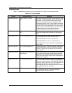
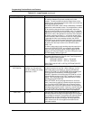
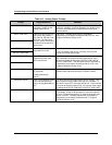
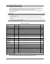
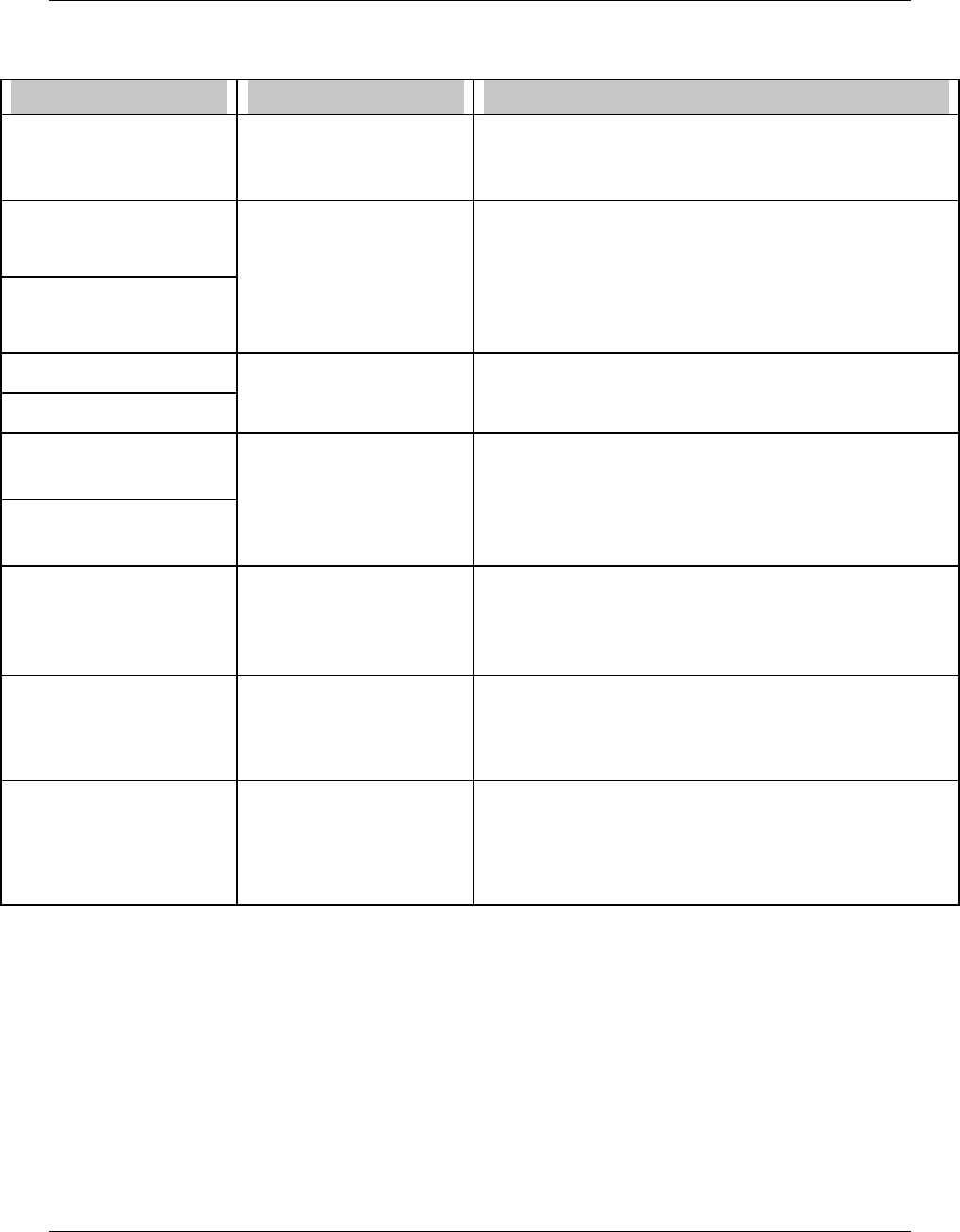
Table 4-13 Analog Output Prompts
Prompt Range/Selections Definition
INPUT SOURCE Enter OFF, analog
parameter, number as the
analog output source.
For a control loop, this is typically set to a control output
(LP# OV). However, it may be directed to any analog value,
such as a calculated value, to retransmit the value to an
external device.
INPUT LOW LIMIT
INPUT HIGH LIMIT
If the AO's input source is a
PID control loop, specify a
high value of 100 and a low
value of 0. For other input
sources, specify limits using
the same units as the AO's
input source.
Input limits. (Variable input limits are available by
programming a constant's Destination with HS or LS. See
Program Constants, Section 4.16.)
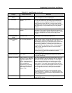
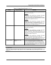
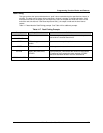
OUTPUT LOW LIMIT
OUTPUT HIGH LIMIT
For CAT, enter any output
range within 0-20 mA
These limits scale the output to the input limits.
For a CAT output a low limit of 4 and high limit of 20 will
provide a 4-20 mA output range.
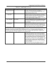
INC SLEW LIMIT
DEC SLEW LIMIT
Enter OFF or 0.1 to 999.9
units/minute (units of the
AO's input source).
Limits the rate of increase or decrease of the analog output.
Value entered is in terms of the AO's input source, not in
terms of the output as defined by OUTPUT LOW LIMIT &
OUTPUT HIGH LIMIT. (Variable slew limits are available by
programming a constant's Destination with IS or DS. See
Program Constants, Section 4.16.)
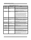
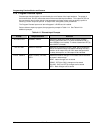
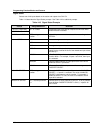
FAILSAFE NONE
UP (Upscale)
DOWN (Downscale)
VALUE
Select failure action to occur on input signal loss. If VALUE is
selected, enter the value desired in FAILSAFE VALUE
FAILSAFE VALUE Enter a value between Input
Low Limit and Input High
Limit or analog parameter or
OFF.
The value at which the output will be held for failsafe. This
value is also the initial output of the loop on "cold start". If
the value is set to OFF, the output will go to 0. Value entered
is in terms of the AO's input source, not in terms of the output
as defined by OUTPUT LOW LIMIT & OUTPUT HIGH LIMIT.
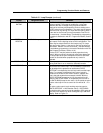
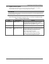
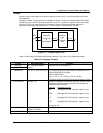
IMPULSE TIME
OFF or ≥ 1
The cycle time (in seconds) for On and Off time of the output.
For example, a time of 150 seconds will cause the output to
be on for 75 seconds and off for 75 seconds when the input
source is at 50%. (Variable impulse time is available by
programming a constant's Destination with IT. Program
Constants, Section 4.16.)