


Programming and Operating Concepts
Video Recorder – User Manual 60
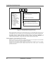
3.14 How to program common configurations
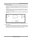
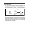
Being able to diagram a control configuration in terms of function blocks makes it easier to program and
configure your instrument for its intended process control application. This function block diagram you
create can be used as a “construction blue print” to program the instrument. Each block in the diagram
relates to a dedicated instrument programming menu in the instrument’s PROGRAM mode.
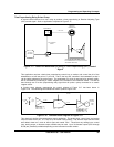
What follows are examples where common control configurations are presented along with their function
block diagrams. The first example is a simple control arrangement in great detail to help you understand
function block diagram basics, followed by more sophisticated examples. Once you understand how to
diagram function blocks, you will be able to draw a diagram for virtually any control strategy regardless of
complexity. Understanding the relationship between such diagrams and the instrument’s programming
menus is key to successfully mastering the instrument’s many capabilities and features.
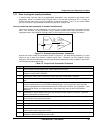
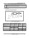
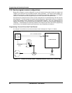
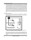
Programming a Current Driven Heat Treat Element
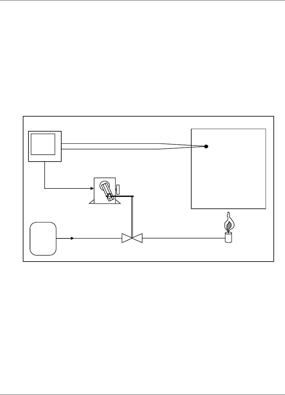
An example of one of the most common and simple control strategies is in Figure 3-11 below.
GAS
SUPPLY
VALVE
BURNER
FURNACE ZONE
TYPE J THERMOCOUPLE
VALVE
ACTUATOR
4 TO 20 mA
(CAT)
PV 200
SP 500
OUT 83.5%
INSTRUMENT
Figure 3-11 Control Of Furnace Zone Temperature With 4-20 mA (CAT) Control Signal