Programming and Operating Concepts
Video Recorder – User Manual 67
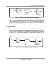
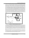
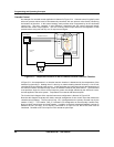
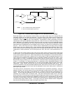
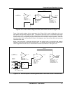
In Figure 3-20, the analog input function block AI1 is depicted processing the resistance values produced
by the RTD. The resulting water temperature measurements (AI1 OV) are then fed to the process
variable input (PV) of the LP1 control loop block. Note how LP1 has been defined as a split output
control loop using the notation “TYPE = SPLIT.” Unique to this control loop is the defined range of its
output value, LP1 OV. Where the standard control loops mentioned thus far have had outputs ranging
exclusively between 0 and 100%, the % values of the split output control loop vary between -100 and
100. 0% is considered the midpoint for this control loop’s output range. When brought on-line, a 0 to
100% output value will be generated by LP1 when hot water is needed to maintain the temperature at set
point. When the addition of cold water is necessary, the loop’s output will assume a value between 0
and -100%. Note that to externalize the control signals generated by LP1, two analog output blocks,
AO1 and AO2, will be used. AO1’s 4 to 20 mA signal will be tied to the hot water valve actuator, while
the actuator that adjusts the position of the cold water valve will receive its mA control signal from AO2.
To provide AO1 and AO2 with usable input driving signals, LP1’s output will be applied to a function
called a “standard splitter (STD SPLITTER).” Made from one of the instrument’s calculated value
function blocks (“CV’s”), the standard splitter will essentially be a mechanism that translates the %
values of the split output control loop into two distinct 0 to 100% signals. They will be applied to the
inputs of AO1 and AO2 and, as such, will drive and linearly correspond with AO1 and AO2’s 4 to 20 mA
outputs.
0-100%
100%
00
100%
100%
CV1 A2
CV1 A1
LP1 OV
AI1
100 Ω
PLATINUM
RTD
AI1 OV
INPUT TYPE = PT100
TYPE = STD SPLITTER
AO1IN
4 TO 20 mA
AO1 BC
AO2
IN
4 TO 20 mA
FB1
FB2
IN
A2
A1
CV1
AO2 BC
FB
LP1
PV
LP1 OV
TYPE = SPLIT
CV1 BC
CV1 A1
CV1 A2
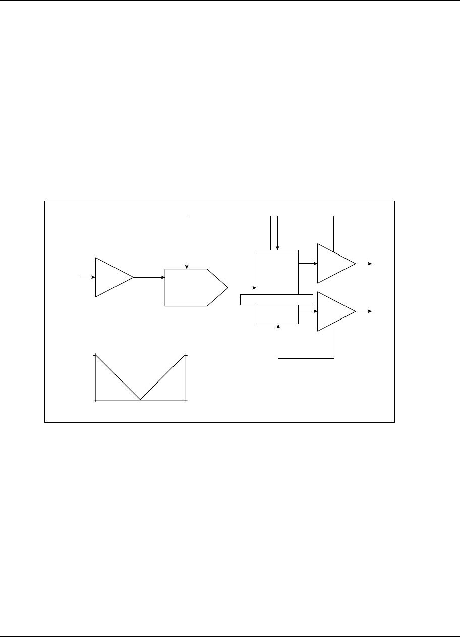
Figure 3-20 Function Block Diagram Of Figure 3-19
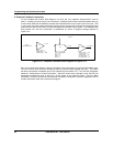
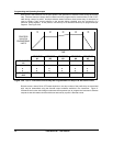
The two outputs on CV1 that will drive AO1 and AO2 are respectively labeled “CV1 A1” and “CV1 A2.”
CV1’s basic operation is described by a plot of these outputs versus LP1 OV. Shown in the lower left of
Figure 3-20, the plot demonstrates that CV1 will produce a 0 to 100% value at its CV1 A1 output when
LP1 calls for an output level between 0 and 100%. CV1 A2 will remain at 0%. When applied to AO1, the
CV1 A1 value will activate the 4 to 20 mA signal needed at the hot water valve actuator to make the
water temperature in the vessel rise. Similarly, when LP1 calls for an output level between 0 and -100%,
CV1 will produce a corresponding 0 to 100% value at CV1 A2. This time, CV1 A1 will remain at 0% and
the CV1 A2 value generated will induce the introduction of cold water into the vessel to cool its contents
down.
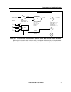
Note the function block diagram’s use of three back calculated feedback paths. Two such paths are
labeled AO1 BC and AO2 BC. They are connected to CV1 from the analog output function blocks at
inputs denoted “FB1” and “FB2.” CV1 BC, the third feedback path, runs from CV1 to the FB input of
LP1. All three feedback paths work together to acknowledge to LP1 that the appropriate output signals
have been generated in response to the % output levels the loop has called for.


