


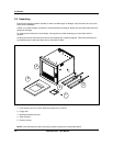
Installation
Video Recorder - User Manual 22
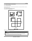
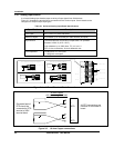
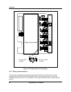
2.5.3 Analog input boards
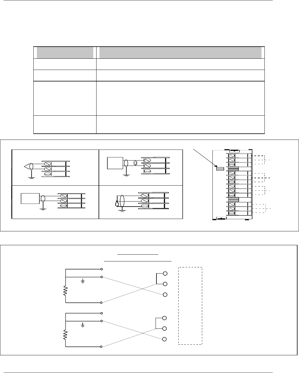
A universal Analog Input board accepts a variety of input signals from field devices.
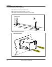
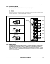
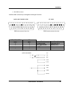
Figure 2-1 illustrates the terminal block connections for the various inputs. One AI board can be
configured to accept multiple input types.
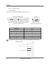
Table 2-1 Universal Analog Input Board Specifications
Specification Description
Input Types mV, V, mA, T/C, RTD, and Ohms
Number of Inputs 4 per board, up to 12 boards per video recorder (48 inputs)
Signal Source Thermocouple with cold junction compensation, for operation
between 0 to 80º C (32 to 176º F)
Line resistance up to 1000 ohms, T/C, mV, mA, V
RTD, 3-wire connections, 40 ohms balanced max.
Input Impedance
10 Meg Ω for T/C, mV inputs,
> 1 Meg Ω for volt inputs
+
-
T/C, mV, V
+
-
*
4 to 20
mA
Source
12
11
10
9
8
7
6
5
4
3
2
1
1
Channel 4
Channel 3
Channel 2
Channel 1
+
-
+
-
+
-
RTD
+
-
RTD
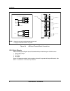
Therm ocouple input
Ground Terminal
RTD Input (3 wires)
+
-
RTD
Current Input m A
*
A 250 ohm resistor is required for the
input range
Ground Terminal
mV, V
Inputs
+
-
mV or V
source
G round Term inal G round Term inal
Slot ID
Figure 2-1 AI Board Terminal Block Connections
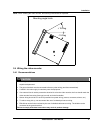
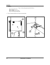
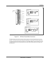
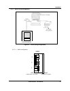
Figure 2-2 10 ohm Copper connections
-
+
RTD
-
+
RTD
10 ohm Copper
with common
g
round lead
Grounded lead of
RTD should be
connected to RTD
terminal of VRX
terminal block
All RTD connections are
common on Universal AI
board.