


3745 FRU Exchange Procedure
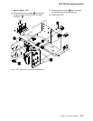
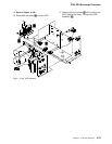
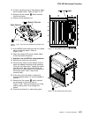
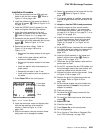
12. At Fan2, disconnect the air flow detector cable
and the power cable. Refer to Figure 4-107.
13. Remove the two screws 1 which maintain
Fan2 to the frame.
14. Slide the Fan2 assembly out.
Figure 4-107. Fan2 Air Flow Detector and Power Con-
nectors
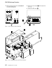
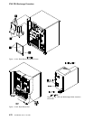
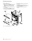
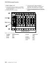
15. At the MOSS board disconnect the four cables
going to the basic board. Refer to
Figure 4-108.
16. Open the clamps which secure these cables
to the basic board enclosure.
17. Attention: Use the ESD kit and procedures.
18. Remove the cross-over connectors.
19. Verify that the cards and the cables from the
cards are labeled according to their positions.
if they are not, label them. Unplug the cables
from the cards, then remove the cards and
store them in a safe place (do not remove the
horizontal cards in row Z, they will be
removed later).
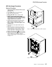
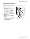
20. At the rear side of the board, remove the
channel tailgate cables if a channel adapter is
installed.
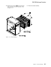
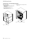
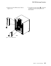
21. Remove the five screws 5 which maintain
the enclosure to the frame (refer to
Figure 4-109). Slide the enclosure out of the
machine taking care not to damage the
cables.
22. Place the enclosure in a safe working area.
Figure 4-108. MOSS to Basic Cable Locations
Figure 4-109. Basic Board Enclosure
Chapter 4. 3745 FRU Exchange 4-79