


3745 FRU Exchange Procedure
Channel Tailgate Exchange Procedure
Removal Procedure
1. Ask the customer to disable the channel
related to the suspected channel tailgate
connector. Also inform him that the 3745
is to be powered OFF.
2. Press Power Off on the control panel.
3. Open the front and rear door.
4. Switch CB1 OFF. Refer to Figure 4-129.
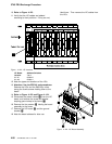
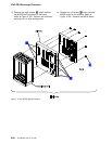
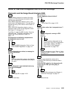
5. Locate the channel tailgate. Refer to
Figure 4-131 on page 4-97.
6. Remove the basic board grid. (two screws
must be removed). Refer to Figure 4-131 on
page 4-97.
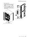
7. At the channel tailgate connectors, set all the
select out bypass switches to Bypass. Refer
to Figure 4-130.
8. Disconnect the channel bus and tag cables
from the channel tailgate connector to be
removed.
9. In order to allow the customer to use the
channel during the repair time, you must
connect the cables together or to the termina-
tors.
10. Remove the two screws which maintain the
channel tailgate connector. See note.
1
11. At the Basic board rear side disconnect the
corresponding flat cables by loosening the
retention screw. These parts are fragile.
Handle them with care.
12. Remove the connector flat cables assembly
from the channel tailgate rack.
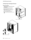
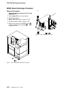
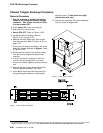
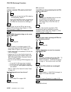
Figure 4-129. CB1 Location
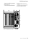
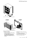
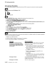
Tag
Bus
Select out
Bypass Switch
Bypass
Normal
Figure 4-130. Select Out Switch
1
An easier access to a lower located channel tailgate connector can be obtained by removing the upper one(s). For each channel
tailgate connector use the steps 10 to 12. Do not disconnect the channel bus and tag cables from the connectors.
4-96 3745 Models 130 to 17A: MIP