


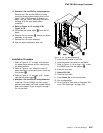
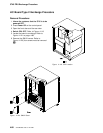

3745 FRU Exchange Procedure
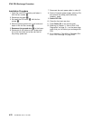
Installation Procedure
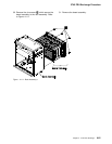
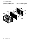
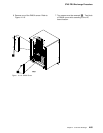
1. Place the new board on the ASM gate and
fasten it with the four screws. 1. Refer to
Figure 4-112 on page 4-82.
2. Install the stiffener on the board and fasten it
with the 14 screws. 9 Refer to Figure 4-112
on page 4-82.
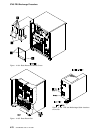
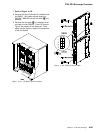
3. Install the DCREG cards (if present) in the
board and tighten them with the retainer.
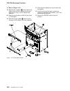
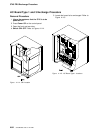
4. Install the board assembly on the rack
assembly and fasten it with the six screws
8. Refer to Figure 4-111 on page 4-81.
5. Reconnect the two ground FDS cables and
fasten them to the rack assembly with the two
screws 7. Refer to Figure 4-110 on
page 4-80.
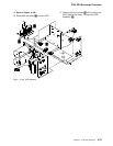
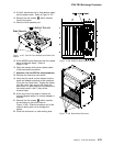
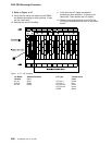
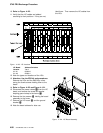
6. Reconnect the other cables. Refer to
Figure 4-110 on page 4-80 and to
Figure 4-113.
Reconnect the cables located in the upper
Y row.
Install on the upper retainer (with four
screws) on these cables.
Reconnect the cables located in the lower
Y row.
Install on retainer (with three screws) on
these cables.
Reconnect the cable in the Z row.
Install on the retainer (with one screw) on
the cable.
7. Press Power Off on the control panel.
Y Row Upper
Y Row Upper
Z Row
Figure 4-113. Y and Z Rows
8. Install the terminator cards and tighten them
with the two retainers (one screw per
retainer). Refer to Figure 4-110 on
page 4-80.
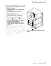
9. Slide the enclosure intoe the machine frame
taking care not to damage the cables.
10. Fasten the enclosure to the frame with the five
screws 5.Refer to Figure 4-109 on
page 4-79.
11. If a channel adapter is installed, reconnect the
channel tailgate cables tot the rear side of the
board.
12. Attention: Use the ESD kit and procedures.
13. Install the cards into their correct location
according to their labels. If you have suspi-
cions about the locations, refer to Figure 4-4
on page 4-6, to Figure 4-5 on page 4-7, or to
Figure 4-6 on page 4-8.
14. Install the cross-over connectors and cables.
If you have suspicions about the cross-over
location, refer to Figure 4-4 on page 4-6,
Figure 4-5 on page 4-7, or Figure 4-6 on
page 4-8.
15. At the MOSS board, reconnect the four cables
from Basic board and close the clamps which
maintain them. Refer to Figure 4-108 on
page 4-79.
16. Install the Fan2 assembly in the frame and
fasten it with the two screws 1. Refer to
Figure 4-107 on page 4-79.
17. Reconnect the air flow detector cable and the
power cable at Fan2.
18. At the PS1 reconnect the four FDS cables and
the multivoltage cable (from basic board) and
close the clamps which maintain them.
19. Reinstall the cover with the two screws. Refer
to Figure 4-106 on page 4-78.
20. Replace the grid of the base board with the
four screws. Refer to Figure 4-83 on
page 4-62.
21. At the channel tailgate, set all the select out
bypass switches to normal (if any channel
adapter is installed).
22. Close the rear door.
23. Re-install the MOSS board covers with the
seven screws 4.
24. Re-install the Basic board cover with the two
screws 2.
25. Switch CB1 ON.
26. Close the front door.
27. Press Power On on the control panel.
28. Run all diagnostics,
29. Go to “Action to Take After a Diagnostic Run
or an FRU Exchange” on page 4-99.
Chapter 4. 3745 FRU Exchange 4-83