


AX2500/2850 Motor Controller User’s Manual 101
Automatic Switching from RS232 to RC Mode
Automatic Switching from RS232 to RC Mode
In many computer controlled application, it may be useful to allow the controller to switch
back to the RC mode. This would typically used to let a user to take over the control of a
robotic vehicle upon computer problem.
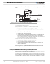
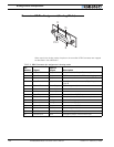
While the AX2500/2850 can operate in either RC Radio or RS232 mode, the RS232 Data
Input and RC Pulse Input 1 share the same pin on the connector. External hardware is
therefore needed to switch this pin from the RS232 source or the RC Radio. The diagram in
Figure 60 shows the external hardware required to perform such a switch.
A third RC channel is used to activate a dual-throw relay. When the radio is Off, or if it is On
with the channel 3 off, the relay contact brings the RS232 signal to the shared input. The
second relay contact maintains the Power Control wire floating, so that the controller
remains on.
When the RC channel 3 is activated, the relay turns On and brings the RC radio signal 1 to
the shared input. The second relay contact brings a discharged capacitor onto the Power
Control wire causing the controller to reset. Resetting the controller is necessary in order
12 Joystick Center 1
MS
00 to FF (06) default Reset
13 Joystick Center 1
LS
00 to FF (40) default Reset
14 Joystick Center 2
MS
00 to FF (06) default Reset
15 Joystick Center 2
LS
00 to FF (40) default Reset
16 Joystick Min 1 MS 00 to FF (11) default Reset
17 Joystick Min 1 LS 00 to FF (30) default Reset
18 Joystick Min 2 MS 00 to FF (11) default Reset
19 Joystick Min 2 LS 00 to FF (30) default Reset
1A Joystick Max 1 MS 00 to FF (0C) default Reset
1B Joystick Max 1 LS 00 to FF (80) default Reset
1C Joystick Max 2 MS 00 to FF (0C) default Reset
1D Joystick Max 2 LS 00 to FF (A8) default Reset
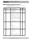
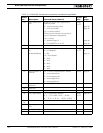
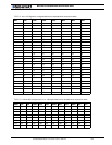
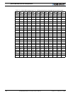
TABLE 18. AX2500/2850 Configuration parameters accessible through RS232
Param
nbr Description Allowed Values (default)
Active
after
See
pages