


AX2500/2850 Motor Controller User’s Manual 127
Control Loop Description
Control Loop Description
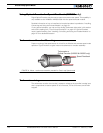
The AX2500/2850 performs the Closed Loop Speed mode using a full featured Propor-
tional, Integral and Differential (PID) algorithm. This technique has a long history of usage in
control systems and works on performing adjustments to the Power Output based on the
difference measured between the desired speed (set by the user) and the actual position
(captured by the tachometer).
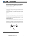
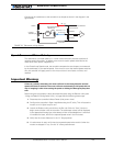
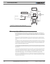
Figure 76 shows a representation of the PID algorithm. Every 16 milliseconds, the control-
ler measures the actual motor speed and subtracts it from the desired position to compute
the speed error.
The resulting error value is then multiplied by a user selectable Proportional Gain. The
resulting value becomes one of the components used to command the motor. The effect
of this part of the algorithm is to apply power to the motor that is proportional with the dif-
ference between the current and desired speed: when far apart, high power is applied,
with the power being gradually reduced as the motor moves to the desired speed.
A higher Proportional Gain will cause the algorithm to apply a higher level of power for a
given measured error thus making the motor react more quickly to changes in commands
and/or motor load.
The Differential component of the algorithm computes the changes to the error from one
16 ms time period to the next. This change will be a relatively large number every time an
abrupt change occurs on the desired speed value or the measured speed value. The value
of that change is then multiplied by a user selectable Differential Gain and added to the out-
put. The effect of this part of the algorithm is to give a boost of extra power when starting
the motor due to changes to the desired speed value. The differential component will also
greatly help dampen any overshoot and oscillation.
The Integral component of the algorithm perform a sum of the error over time. This compo-
nent helps the controller reach and maintain the exact desired speed when the error is
reaching zero (i.e. measured speed is near to, or at the desired value).