


AX2500/2850 Motor Controller User’s Manual 27
Controller Power
that connecting one wire of a given battery potential will eliminate the need for connecting
the other. Malfunction or even damage may occur if one wire is assuming the load of all
two.
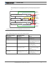
TABLE 4. Effect of Power Control under various voltage conditions
Power Control input is
connected to
And Main Battery
Voltage is Action
Ground Any Voltage from 0V to 40V Controller is Off
Floating Below 9V Controller is Off
Floating Between 9V and 10.5V Controller Logic is On
Power Stage is Disabled (under-
voltage condition)
Floating Between 10.5 and 40V Controller is On. Drawing power
from Main Battery
Power Stage is Active
10.5V to 40V Lower than Voltage on Power
Control input - or Off
Controller is On. Drawing power
from external source (backup
battery)
Power Stage is Active
10.5V to 40V Higher than Voltage on Power
Control input
Controller is On. Drawing power
from Main Battery
Power Stage is Active
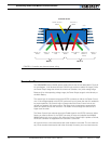
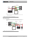
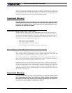
Channel 1 MOSFET Power Stage
Channel 2 MOSFET Power Stage
5Vmin
40V max
Microcomputer &
MOSFET Drivers
9.5V min
13V max
DC/DC
ENABLE
10.5V min
40V max
5Vmin
40V max
Power
Control
&Backup
VBatt Vmot
Mot1(-)
Mot2(-)
Mot1(+)
Mot2(+)
VBatt Vmot
GND
GND
GND
FIGURE 9. Representation of the AX2500/2850’s Internal Power Circuits