


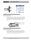

Connecting Power and Motors to the Controller
32 AX2500/2850 Motor Controller User’s Manual Version 1.7. February 1, 2005
Important Warning
Avoid switching Off or cutting open the main power cables (thick black and red
wires) while the motors are spinning. Damage to the controller may occur.
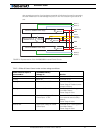
Overvoltage Protection
The AX2500/2850 includes a battery voltage monitoring circuit that will cause the output
transistors to be turned Off if the main battery voltage applied on the thick red and black
wires rises above 43V.
This protection is designed to prevent the voltage created by the motors during regenera-
tion to be “amplified” to unsafe levels by the switching circuit.
The controller will resume normal operation when the measured voltage drops below 43V.
Undervoltage Protection
In order to ensure that the power MOSFET transistors are switched properly, the AX2500/
2850 monitors the internal 12V power supply that is used by the MOSFET drivers. If the
internal voltage drops below 10V, the controller’s output stage is turned Off. The rest of the
controller’s electronics, including the microcomputer will remain operational as long as the
internal voltage is above 8V.
The internal voltage will be the output of the DC/DC converter which will be a solid 12V as
long as either of the main battery or backup voltage is higher than 12.5V. If the main and
backup voltage drop below 12.V, the DC/DC converter’s output will be approximately 0.5V
lower than the higher of the main or backup voltage.
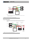
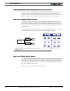
Using the Controller with a Power Supply
Using a transformer or a switching power supply is possible but requires special care as
the current will want to flow back from the motors to the power supply during regenera-
tion. As discussed in “Power Regeneration Considerations” on page 31, if the supply is not
able to absorb and dissipate regenerated current, the voltage will increase until the over-
voltage protection circuit cuts off the motors. While this process should not be harmful to
the controller, it may be to the power supply, unless one or more of the protective steps
below are taken:
• Use a power supply that will not suffer damage in case that a voltage is applied at
its output that is higher than the transformer’s own output voltage. This information
is seldom published in commercial power supplies, so it is not always possible to
obtain positive reassurance that the supply will survive such a condition.
• Avoid deceleration that is quicker than the natural deceleration due to the friction in
the motor assembly (motor, gears, load). Any deceleration that would be quicker
than natural friction means that braking energy will need to be taken out from the
system, and cause a reverse current flow and voltage rise. See “Programmable
Acceleration” on page 40.
• Place a battery in parallel with the power supply output. This will provide a reservoir
into which regeneration current can flow. It will also be very helpful for delivering