


AX2500/2850 Motor Controller User’s Manual 15
Powering On the Controller
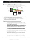
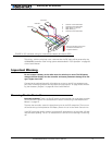
This wiring - with the wire loop uncut - assumes hat the R/C radio will be powered by the
AX2500/2850 controller. Other wiring options are described in “R/C Operation” on page 69
of the User’s Manual.
Important Warning
Do not connect a battery to the radio when the wire loop is uncut. The RC battery
voltage will flow directly into the controller and cause permanent damage if its volt-
age is higher than 5.5V.
Connecting the optional channel 3 will enable you to turn on and off two accessory out-
puts. See “Connecting Sensors and Actuators to Input/Outputs” on page 49 and “Activat-
ing the Accessory Outputs” on page 83 of the User’s Manual.
Powering On the Controller
Important reminder: There is no On-Off switch on the controller. You must insert a switch
on the controller’s power wire as described in section“Connecting to the Batteries and
Motors” on page 13.
To power the controller, center the joystick and trims on the R/C transmitter. Then turn on
the switch that you have placed on the Battery Power wire or on the Power Control wire.
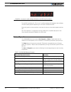
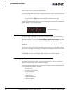
If the R/C transmitter and/or receiver is powered off, the display on the controller will alter-
nate the letters spelling “no ctrl” to indicate that it is On but is not receiving a control sig-
nal.
8
9
15
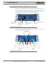
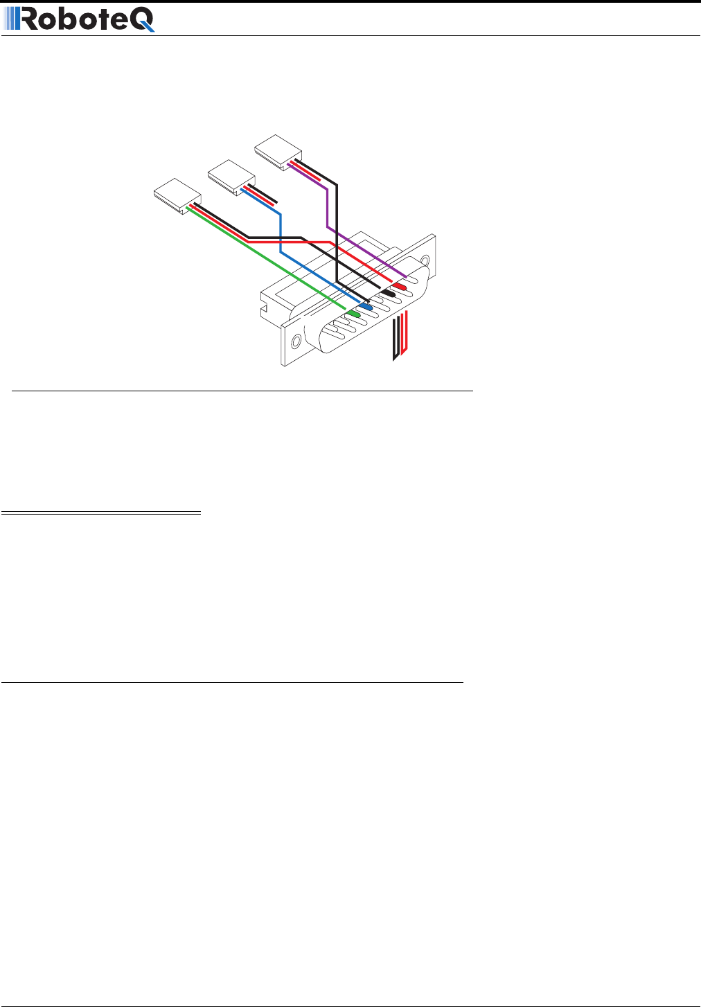
Pin 1
Channel 1
Wire loop bringing power from
controller to RC radio and
to optical isolators
Channel 2
3: Channel 1 Command Pulses
4: Channel 2 Command Pulses
6: Radio battery (-) Ground
7: Radio battery (+)
8: Channel 3 Command Pulses
Channel 3
FIGURE 4. R/C connector wiring for 3 channels and battery elimination (BEC)