


Connecting Power and Motors to the Controller
28 AX2500/2850 Motor Controller User’s Manual Version 1.7. February 1, 2005
Powering the Controller using the Motor Batteries
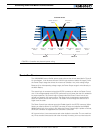
The AX2500/2850 included a DC/DC converter to generate the internal 12V required for its
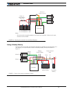
operation. The diagram on Figure 10 show how to wire the controller to a single battery cir-
cuit and the two options for turning the power On and Off. The diagram shows two
switches, although switching either one alone will power the controller Off.
In a typical configuration, it is recommended that the Motor Power be always applied and
that the Controller’s Power be controlled using a switch on the Power Control wire (yellow).
When the controller is Off, the output transistors are in the Off position and no power is
drawn on the Motor Power battery.
For safety reasons, however, it is highly recommended that a way of quickly disconnecting
the Motor Power be provided in the case of loss of control and all of the AX2500/2850
safety features fail to activate
Note, however, that eventually the motor batteries will get weaker and the voltage drop
below the level needed for the internal DC/DC converter to properly operate. For all profes-
sional applications it is therefore recommended to add a separate 12V (to 40V) power sup-
ply to ensure proper powering of the controller under any conditions.
Important Warning
Unless you can ensure a steady 12V voltage in all conditions, it is recommended that
the battery used to power the controller’s electronics must be separate from the one
used to power the motors. This is because it is very likely that the motor batteries
will be subject to very large current loads, which may cause the voltage to eventually
dip below 12V as the batteries’ charge drops. The separate backup power supply
should be connected to the Power Control input.
Important Warning
On versions of the AX2550 with PCB revision number lower than 5.2, the backup
power supply applied on the Power Control wire must NEVER EXCEED 13V. Perma-
nent damage may otherwise occur. PCB revision number can be found on the sticker
on the case’s bottom.