


General Operation
46 AX2500/2850 Motor Controller User’s Manual Version 1.7. February 1, 2005
Special Use of Accessory Digital Inputs
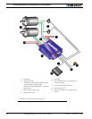
The AX2500/2850 includes two general purpose digital inputs identified as Input E and
Input F. On the AX2850, input E is disabled. The location of these inputs on the DB15 con-
nector can be found in the section “I/O List and Pin Assignment” on page 52, while the
electrical signal needed to activate them is shown on “Connecting Switches or Devices to
Input F” on page 55.
By default, these inputs are ignored by the controller. However, the AX2500/2850 may be
configured to cause either of the following actions:
• Activate the buffered Output D (Output D is not available when Encoder module is
installed)
• or Turn Off/On the power MOSFET transistors
These alternate modes can only be selected using the Roborun Utility (see “Controls Set-
tings” on page 163. Each of these modes is detailed below.
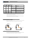
Using the Inputs to Activate the Buffered Output
When this setting is selected, the buffered Output C will be On when the Input line is
pulled to Ground (0V). The Output will be Off when the Input is pulled high.
This function makes it possible to drive solenoids or other accessories up to 2A at 24V
using a very low current switch, for example.
Using the Inputs to turn Off/On the Power MOSFET transistors
When this setting is selected, the controller’s Power MOSFET transistors will be active,
and the controller will be operating normally, only when the input is pulled to ground.
When the input is pulled high, all the power MOSFETs are turned Off so that the motors
are effectively disconnected from the controller.
This function is typically used to create a “dead man switch” when the controller is driven
using an analog joystick. The motors will be active only while the switch is depressed. If
the switch is left off for any reason, the motors will be disconnected and allowed to free-
wheel rather than coming to an abrupt stop.
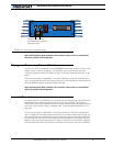
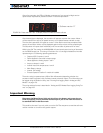
Self-Test Mode
The AX2500/2850 incorporates a simple Self-Test mode that performs the following func-
tions:
• Display the software revision number on the LED display
• Ramp each motor up and down in both directions
• Internal parameters on the serial port output
The Self Test mode can be conveniently initiated using only the controller’s switches so
that no radio or computer is needed.
To enter the Self Test mode, press and hold the Set button while resetting or powering up
the controller.