


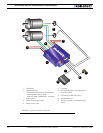
Connecting Sensors and Actuators to Input/Outputs
54 AX2500/2850 Motor Controller User’s Manual Version 1.7. February 1, 2005
When the controller is used in RS232 mode, this output can be turned On and Off using
the !C (On) and !c (Off) command strings. See “RS232 Commands Set” on page 92 for
more information.
Important warning:
This output is unprotected. If your load draws more than 2A, permanent damage
may occur to the power transistor inside the controller. A 1A fuse may be used in
series with the load for increased protection.
Overvoltage spikes induced by switching inductive loads, such as solenoids or
relays, will destroy the transistor unless a protection diode is used.
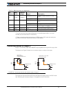
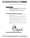
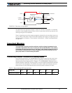
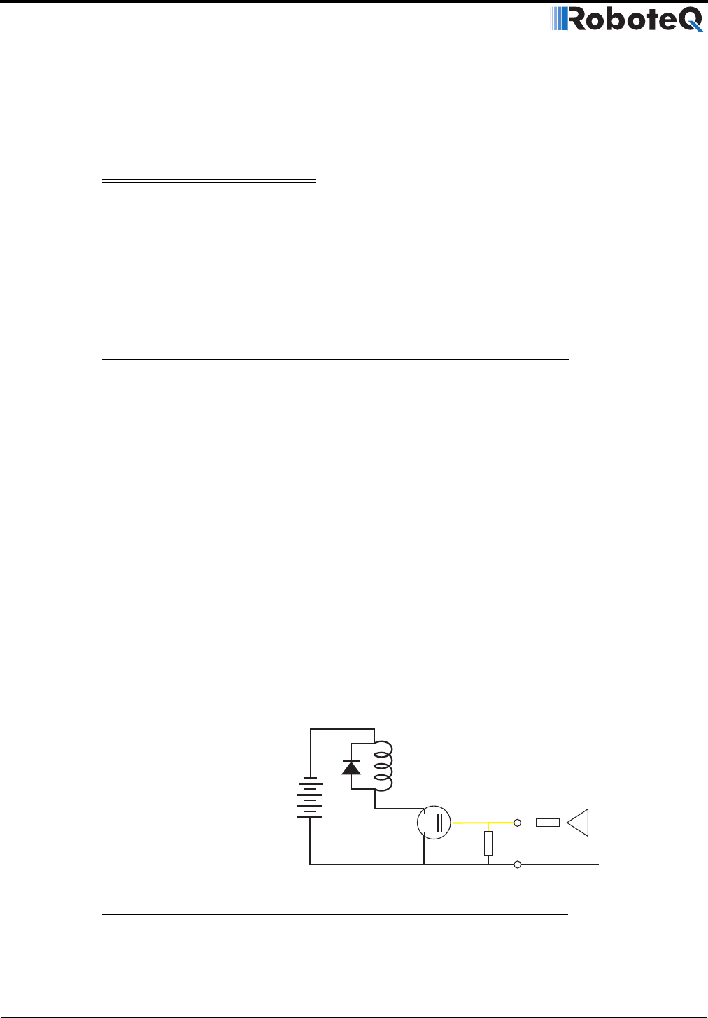
Connecting devices to Output D
Output D is a low-current, unbuffered output. When Off, this output will be pulled to
ground through a 10Kohm resistor. When On, this output will be pulled to around 4.5V
through that same resistor.
The D output cannot drive any load directly and requires an external transistor or solid state
relay to drive high current accessories. Because they are external, the size, voltage, and
power of these transistors can be selected to best suit a particular need.
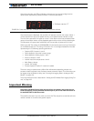
The diagram on Figure 24 shows how to drive a large inductive load using the D output and
a Power MOSFET widely available at most electronic component distributors. The MOS-
FET must conduct with a gate voltage of 4V or higher.
The D output can be toggled On and Off using the Channel 3 Joystick when in the R/C
mode. See “Activating the Accessory Outputs” on page 83 for more information.
When the controller is used in RS232 mode, this output can be turned On and Off using
the !D (On) and !d (Off) command strings. See “RS232 Commands Set” on page 92 for
more information.
5 to
24V
DC
1MOhm
10kOhm
AX2500 Internal
Buffer and Resistor
Output D 12
IRF1010
Use Diode for Relay, Valve
Motor, Solenoid
or other Inductive Load
Ground 5
+
-
FIGURE 24. Connecting external MOSFET and load to Output D