


Serial (RS-232) Controls and Operation
104 AX2500/2850 Motor Controller User’s Manual Version 1.7. February 1, 2005
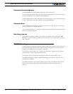
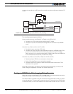
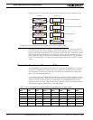
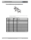
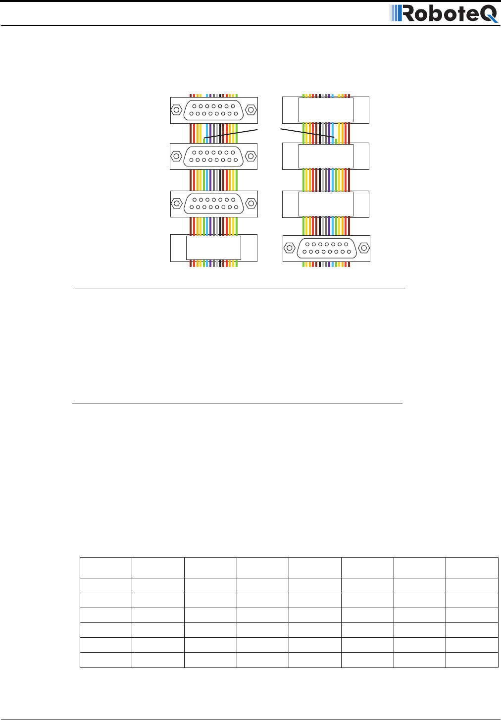
logging purposes. This cable has a 15-pin male connector and 3 15-pin connectors. The
male connector plugs into the controller. The application cable that would normally plug
into the controller may now be plugged into one of the adapter’s female connector 2. The
PC can be plugged into connector 3 or 4. Connector 3 has the Rx and Tx data lines needed
for full duplex serial communication, thus allowing the PC to send commands to the con-
troller. Connector 4 has the Rx line cut so that only a data flows only from the controller to
the PC. This configuration is for capturing the data logging strings sent in the RC or Analog
modes.
Decimal to Hexadecimal Conversion Table
The AX2500/2850 uses hexadecimal notation for accepting and responding to numerical
commands. Hexadecimal is related to the binary system that is used at the very heart of
microcomputers. Functions for converting from decimal to hexadecimal are readily avail-
able in high level languages such as C.
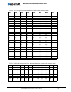
If you intend to enter commands manually using the terminal emulation program, you can
use the conversion table in Table 19 to do the translation. Note that the table only shows
numbers for 0 to 127 decimal (00 to 7F hexadecimal). The AX2500/2850’s speed com-
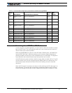
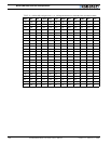
mands are within this range. Table 20 shows the conversion values for numbers between
128 and 255 (unsigned) and between -1 and -128 (signed)
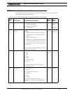
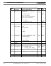
TABLE 19. 0 to +127 signed or unsigned decimal to hexadecimal conversion table
DecHexDecHexDecHexDecHex
0 00322064409660
1 01332165419761
2 02342266429862
3 03352367439963
4 043624684410064
5 053725694510165
Male to controller
Female to PC with RxData Only
Cut
Wire
Front View Rear View
Female to PC with Rx and Tx Data
Female to Application
1
1
1
1
1
2
3
4
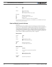
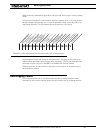
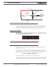
FIGURE 62. ASCII string sent by the controller while in R/C or Analog mode