AX2500/2850 Motor Controller User’s Manual 103
Data Logging Cables
DB15 connector is described on page 85 for the R/C mode, and on page 113 for the Analog
mode.
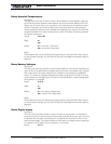
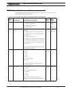
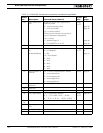
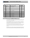
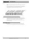
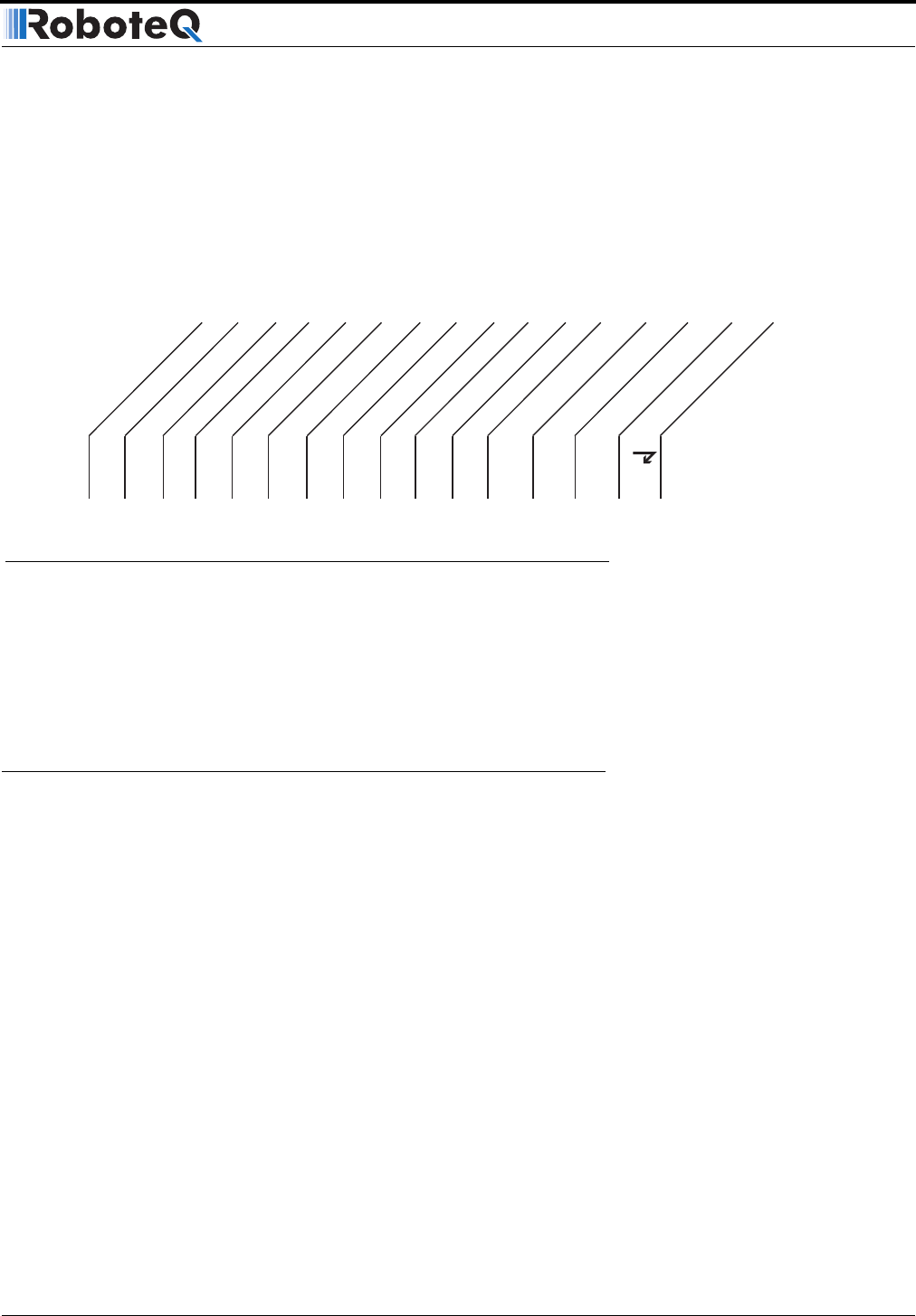
This string is composed of a start character delimiter, followed by 12 or 13 two-digit Hexa-
decimal numbers representing 12 or 13 internal parameter values, and ending with a Car-
riage Return character. The figure below shows the structure of this string.
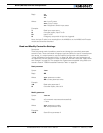
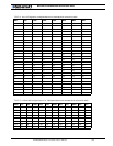
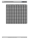
The hexadecimal values and format for each parameter is the same as the response to
RS232 queries described starting on page 93 in this section. The Encoder Speed/Position
parameter is output only on the AX2850 or the AX2550 with Encoder module.
Characters are sent by the controller at the rate of one every 8ms. A complete string is
sent in 213ms or 224ms.
Data Logging Cables
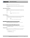
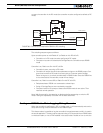
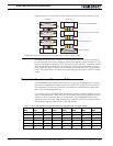
The wring diagrams shown in the figures below describe an easy-to-assemble cable
assembly for use to create insertion points where to connect the PC for debug and data
: 00 11 22 33 44 55 66 77 88 99 AA BB CC
Start Delimiter
End Delimiter
Command 1
Command 2
Output Power 1
Output Power 2
Analog In 1
Analog In 2
Amps 1
Amps 2
Temperature 1
Temperature 2
Main Batt Volts
Internal Volts
Encoder Spd/Pos
FIGURE 61. ASCII string sent by the controller while in R/C or Analog mode


