


AX2500/2850 Motor Controller User’s Manual 135
Connecting the Encoder
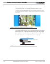
4- Slide the cover back on. Install the new face plate
5- Power on the controller and install version 1.6 or newer of the controller firmware and PC
utility. Update the encoder firmware if a new version exists.
Connecting the Encoder
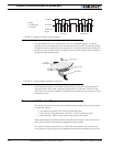
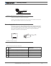
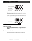
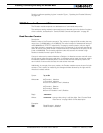
The Encoder module uses a widely available 8-pin RJ45 connector identical to these found
on all Ethernet devices. The connector provides 5V power to the encoders and has inputs
for the two quadrature signals from each encoder. Using multi-level signaling, it is also pos-
sible to share the quadrature inputs with limit switches. The figure and table below
describes the connector and its pin assignment.
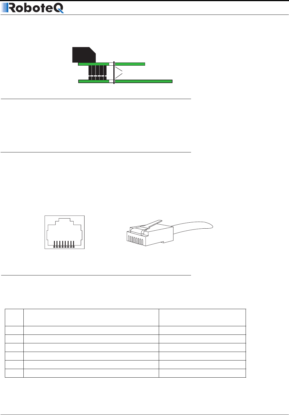
TABLE 23. Encoder connector pin descriptions
Pin Name
Cable Color
(when using standard network cable)
1 Encoder 2 - Channel B. Optional Limit Switch 4 Orange/White
2 Encoder 2 - Channel A. Optional Limit Switch 3 Orange
3 Ground Green/White
45V Out Blue
5 Encoder 1 - Channel B. Optional Limit Switch 2 Blue/White
6 Encoder 2 - Channel A. Optional Limit Switch 1 Green
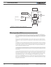
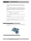
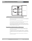
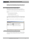
Solder wire
Encoder Module
Main Board
FIGURE 82. Solder wire for more robust assembly
1
1
8
8
FIGURE 83. Encoder connector