


AX2500/2850 Motor Controller User’s Manual 131
Optical Incremental Encoders Overview
SECTION 12 Installing,
Connecting and
Using the
Encoder Module
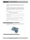
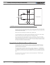
This section describes the Encoder input module that is factory installed inside the
AX2850, or that may be added onto the AX2550.
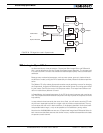
Optical Incremental Encoders Overview
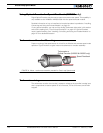
Optical incremental encoders are a mean for capturing speed and travelled distance on a
motor. Unlike absolute encoders which give out a multi-bit number (depending on the reso-
lution), incremental encoders output pulses as they rotate. Counting the pulses tells the
application how many revolutions, or fractions of, the motor has turned. Rotation velocity
can be determined from the time interval between pulses, or by the number of pulses
within a given time period. Because they are digital devices, incremental encoders will
measure distance and speed with perfect accuracy.
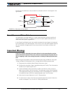
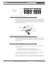
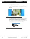
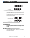
Since motors can move in forward and reverse direction, it is necessary to differentiate the
manner that pulses are counted, so that they can increment or decrement a position
counter in the application. Quadrature encoders have dual channels, A and B, which are
electrically phased 90° apart. Thus, direction of rotation can be determined by monitoring
the phase relationship between the two channels. In addition, with a dual-channel encoder,
a four times multiplication of resolution can be achieved by counting the rising and falling
edges of each channel (A and B). For example, an encoder that produces 250 Pulses per
Revolution (PPR) can generate 1,000 Counts per Revolution (CPR) after quadrature.