


Serial (RS-232) Controls and Operation
102 AX2500/2850 Motor Controller User’s Manual Version 1.7. February 1, 2005
to revert the controller in the RC mode (the controller must be configured to default to RC
mode).
The switching sequence goes as follows:
Upon controller power on with Radio off: (or Radio on with RC ch3 off)
• Controller run in RC mode (must be configured in RC mode)
• Computer must send 10 consecutive Carriage Returns. Controller enters RS232
mode
Controller is on, Radio urns On with RC ch3 On
• Controller is reset, returning to RC mode
• Controller will output the continuous parameter strings on the RS232 output.Com-
puter thus knows that RC mode is currently active. Computer sends Carriage
Return strings to try to switch controller back in RS232 mode. Since the RS232 line
is not connected to the controller, mode will not change
Controller is on, Radio is turned Off (or Radio On with RC ch3 Off)
• Relay deactivates. RS232 now connected to shared input
• String of Carriage Returns now received by controller.
• Computer looks for OK prompt to detect that RS232 mode is now active. Then
resumes normal operation.
Note: Wait 5 seconds for the capacitor to discharge before attempting to switch to RC
mode if doing this repeatedly. Controller will not reset otherwise.
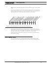
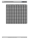
Analog and R/C Modes Data Logging String Format
When the controller is configured in R/C or Analog mode, it will automatically and continu-
ously send a string of ASCII characters on the RS232 output.
This feature makes it possible to log the controller’s internal parameters while it is used in
the actual application. The data may be captured using a PC connected via an RS232 cable
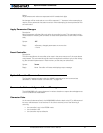
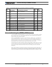
or wireless modem, or into a PDA installed in the actual robot. Details on how to wire the
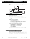
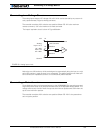
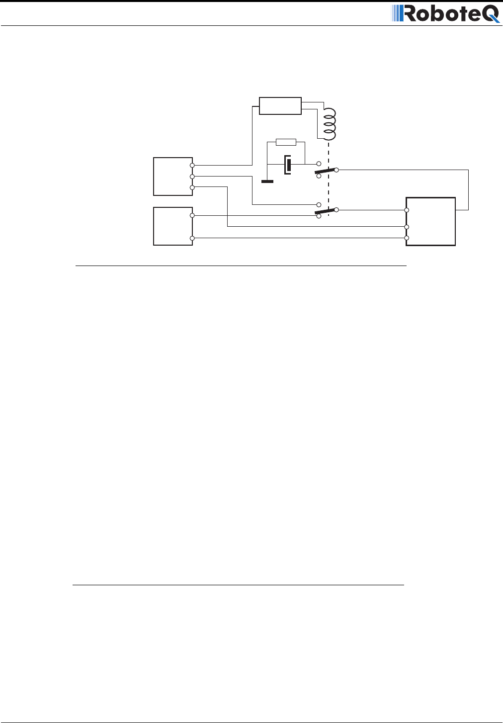
RC3
RC1
RC2
TxData
RxData TxData
RC2/InputF
RC1/RxData
Power Control
Controller
4.7k
220uF
RC Radio
Computer
RC Activated
Switch
FIGURE 60. External circuit required for RS232 to RC switching