


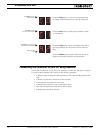
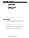
Connecting Power and Motors to the Controller
26 AX2500/2850 Motor Controller User’s Manual Version 1.7. February 1, 2005
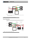
Controller Power
The AX2500/2850 uses a flexible power supply scheme that is best described in Figure 9.
On this diagram, it can be seen that the Control Logic requires a stable 12V supply, while
the Power Output stage that drives the motors can tolerate a very wide voltage range.
Because of its wide operating voltage range, the Power Output stage is wired directly to
the Main Battery.
The control logic is connected to both the DC/DC converter as well as the Power Control
wire. If the voltage applied to the DC/DC converter’s input is lower than the 12V needed for
its proper operation, the Control Logic will stop unless the Power Control wire is con-
nected to a separate 12V power source. The diode circuit is designed to automatically
select one power source over the other. The diodes will let through the source that is
higher than the other.
The Power Control input also serves as the Enable signal for the DC/DC converter. When
floating or pulled to above 1V, the DC/DC converter is active and supplies the AX2500/
2850’s control logic, thus turning it On. When the Power Control input is pulled to Ground,
the DC/DC converter is stopped and the controller is turned Off.
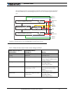
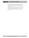
All 3 ground wires (-) are connected to each other inside the controller. The two main bat-
tery wires are also connected to each other internally. However, you must never assume
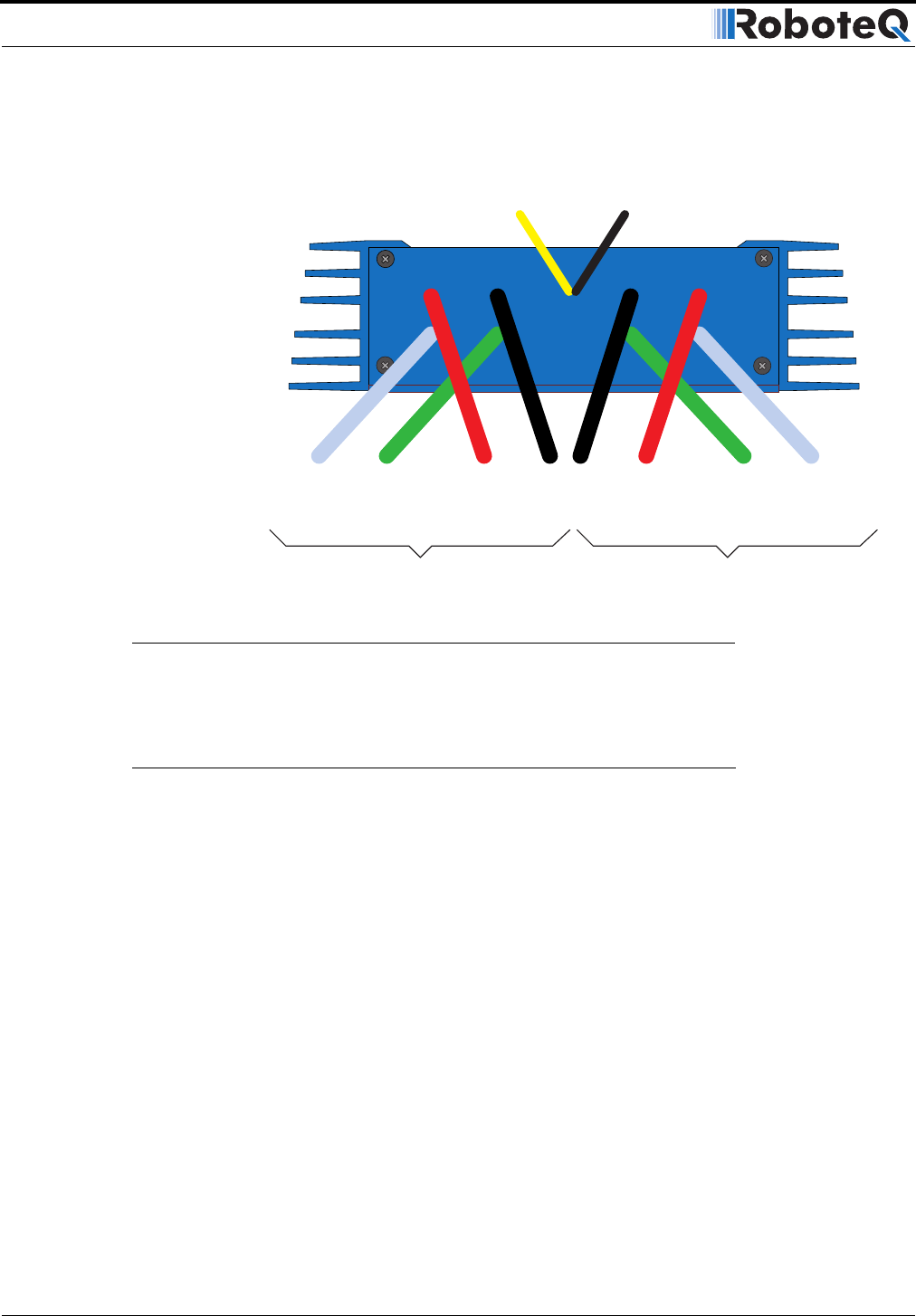
Controller Power
Ground (-)
Black
(top)
Power Control
Ye l l ow
Motor 2
12 to 40V (+)
Red
Ground (-)
Black
Motor(+)
Yellow or
White
Motor (-)
Green
Motor 1
12 to 40V (+)
Red
Motor (-)
Green
Motor (+)
White
FIGURE 8. Controller rear plate and power wiring