


Connecting Sensors and Actuators to Input/Outputs
56 AX2500/2850 Motor Controller User’s Manual Version 1.7. February 1, 2005
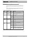
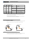
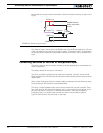
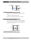
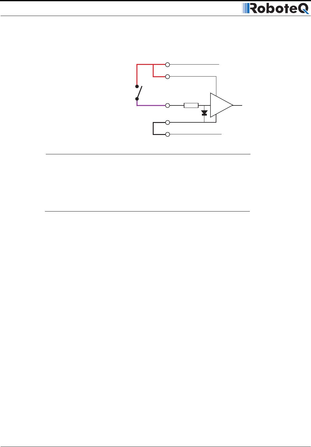
be activated by a simple switch connected to +5V and no external resistor, as show in the
Figure.
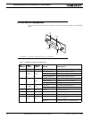
The status of Input F can be read in the RS232 mode with the ?i command string. The con-
troller will respond with three sets of 2 digit numbers. The status of Input F is contained in
the second set of numbers and may be 00 to indicate an Off state, or 01 to indicate an On
state.
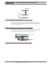
Connecting Switches or Devices to EStop/Invert Input
This input is used to connect various switches or devices depending on the selected con-
troller configuration.
The factory default for this input is “No Action”.
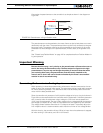
This input can also be configured to be used with an optional “inverted” sensor switch.
When activated, this will cause the controls to be inverted so that the robot may be driven
upside-down.
When neither Emergency Stop or Inverted modes are selected, this input becomes a gen-
eral purpose input like the other two described above.
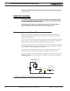
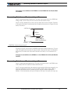
This input is a high impedance input with a pull-up resistor built into the controller. There-
fore it will report an On state (no emergency stop, or not inverted) if unconnected. A sim-
ple switch as shown on Figure 27 is necessary to activate it. Note that to trigger an
Emergency Stop, or to detect robot inversion this input must be pulled to ground.
Figure 27 show how to wire the switch to this input.
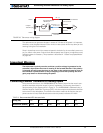
10kOhm
AX2500 Internal
Buffer equivalent
Circuit
Input F 4
+5V Out 14
+5V In 7
GND Out 5
GND In 6
Opto
FIGURE 26. Switch wiring to Input F