


AX2500/2850 Motor Controller User’s Manual 13
Connecting to the Batteries and Motors
Connecting to the Batteries and Motors
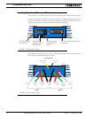
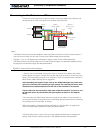
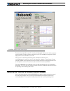
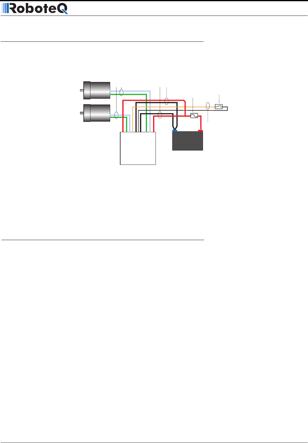
Connection to the batteries and motors is shown in the figure below and is done by con-
necting the set of wires coming out from the back of the controller.
1- Connect the two thick black wires to the minus (-) terminal of the battery that will be
used to power the motors. Connect the two thick red wires to the plus (+) terminal of the
battery. The motor battery may be of 12 to 40 Volts. There is no need to insert a switch on
Motor Power cables, although one is suggested.
Avoid extending the length of these wires as the added inductance may cause dam-
age to the controller when operating at high currents. Try extending the motor wires
instead since the added inductance on this side of the controller is not harmful.
The two red wires are connected to each other inside the controller. The same is true
for the black wires. You should wire each pair together as shown in the diagram
above.
2- You may leave the yellow Power Control wire and the thin black wire unconnected, or
you may connect them to a power switch. If left floating, protect these wires from touching
any metallic part of the controller or chassis.
Refer to the chapter “Connecting Power and Motors to the Controller” on page 25 for
more information about batteries and other connection options.
3- Connect each motor to one of the two output cables pair. Make sure to respect the
polarity, otherwise the motor(s) may spin in the opposite direction than expected
12V to 40V
Motor Battery
Optional
Power on/off
switch
Motor
Cables
Battery
Power Cables
Power Control
Wire
-
-
+
+
Motor1
Motor2
Controller
Fuse
Notes:
- The Battery Power connection are doubled in order to provide the maximum current to the controller. If
only one motor is used, only one set of motor power cables needs to be connected
- Typically, 1, 2 or 3 x 12V batteries are connected in series to reach 12, 24 or 36V respectively
- The Power Control wire may be used to turn On and Off the controller, or to provide a separate and sta-
ble supply to the controller’s logic (See discussion below)
FIGURE 3. Electrical Power Wiring Diagram