


R/C Operation
76 AX2500/2850 Motor Controller User’s Manual Version 1.7. February 1, 2005
power voltage are still separate, some protection remains should the controller fail and
accidentally generate a high voltage on its +5V output.
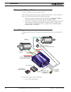
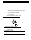
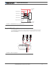
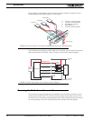
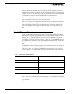
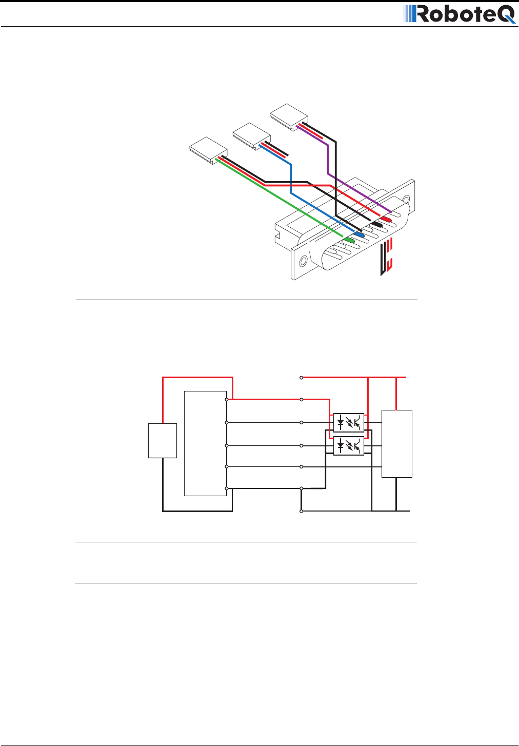
Figure 46 shows the cabling of the R/C radio to the controller when Channel 3 is used and
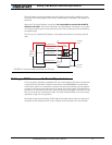
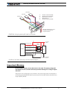
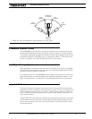
partial optical isolation is desired. Figure 47 shows the equivalent electrical diagram.
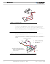
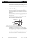
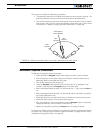
Powering the Radio from the controller
The 5V power and ground signals that are available on the controller’s connector may be
used to power the R/C radio. The wire loop is used to bring the controller’s power to the
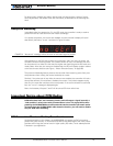
the radio as well a for powering the optocoupler stage. Figure 48 below shows the connec-
tor wiring necessary to do this. Figure 49 shows the equivalent electrical diagram.
8
9
15
Pin 1
Channel 1
Channel 2
3: Channel 1 Command Pulses
4: Channel 2 Command Pulses
6: Radio battery (-) Ground
7: Radio battery (+)
8: Channel 3 Command Pulses
Channel 3:
Cut red loop
FIGURE 46. Wiring when Ch 3 is used with radio powered by its own separate battery
Controller
Power
R/C Radio Power
Opto-
Isolators
Radio
Battery
R/C Radio
MCU
R/C Channel 1
R/C Channel 2
R/C Radio Ground
Controller
Ground
R/C Channel 3
14
3
7
8
6
5-13
4
FIGURE 47. Partial opto-isolation with Channel 3 electrical diagram