


AX2500/2850 Motor Controller User’s Manual 53
Connecting devices to Output C
*The wire colors are those used by Roboteq on our prefabricated cables. It is recom-
mended you use these colors for consistency.
**These connections should only be done in RS232 mode or R/C mode with radio pow-
ered from the controller. Otherwise connect to radio battery.
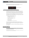
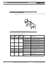
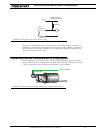
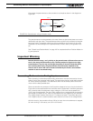
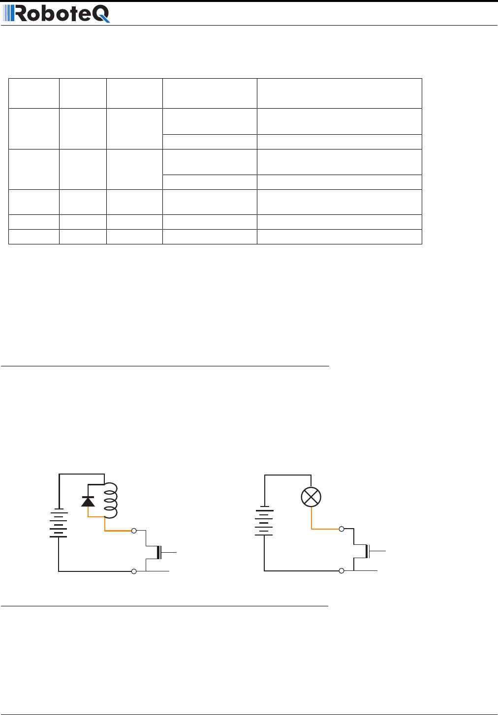
Connecting devices to Output C
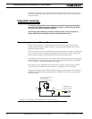
Output C is a buffered, Open Drain MOSFET output capable of driving over 2A at up to 24V.
The diagrams on Figure 23 show how to connect a light or a relay to this output:
This output can be turned On and Off using the Channel 3 Joystick when in the R/C mode.
See “Activating the Accessory Outputs” on page 83 for more information.
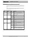
10 Green Analog in
RC/RS232: Ana in 2 Channel 2 speed, position or temp
input
Analog: Command 2 Analog command for channel 2
11 Blue Analog in RC/RS232: Ana in 1 Channel 1 speed, position or temp
input
Analog: Command 1 Analog command for channel 1
12 Yellow Output Output D Low Current Accessory Output D -
(Not available on AX2850)
14 Red Power Out +5V +5V Power Output (100mA max.)
15 Brown Input Input EStop/Inv Emergency Stop or Invert Switch input
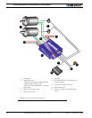
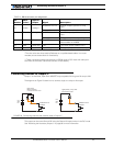
TABLE 12. DB15 connector pin assignment
Pin
Number
Wire
Color*
Input or
Output Signal Description
5 to
24V
DC
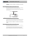
Output C 1,9
AX2500 Internal
MOSFET
Relay, Valve
Motor, Solenoid
or other Inductive Load
Ground 5
+
-
5 to
24V
DC
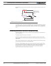
Output C 1,9
AX2500 Internal
MOSFET
Lights, LEDs, or any other
non-inductive load
Ground 5
+
-
FIGURE 23. Connecting inductive and resistive loads to Output C