


AX2500/2850 Motor Controller User’s Manual 125
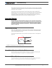
Speed Sensor and Motor Polarity
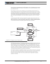
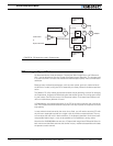
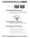
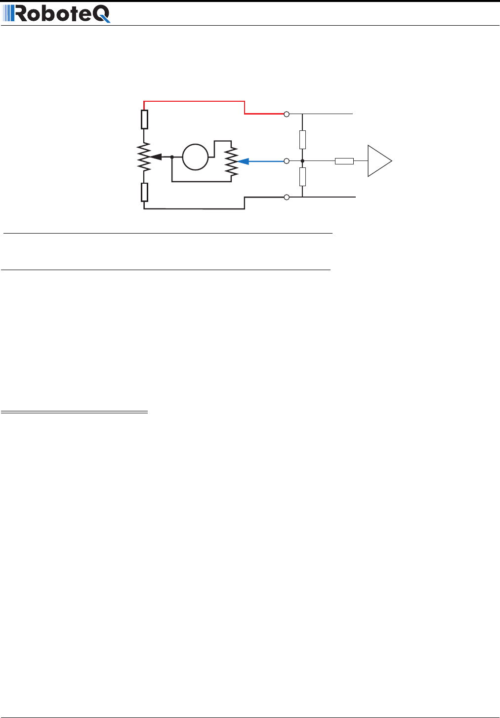
Connecting the tachometer to the controller is as simple as shown in the diagram in the
figure below.
Speed Sensor and Motor Polarity
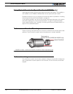
The tachometer or encoder polarity (i.e. which rotation direction produces a positive of
negative speed information), is related to the motor’s rotation speed and direction the
motor turns when power is applied to it.
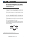
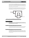
In the Closed Loop Speed mode, the controller compares the actual speed, as measured
by the tachometer, to the desired speed. If the motor is not at the desired speed and direc-
tion, the controller will apply power to the motor so that it turns faster or slower, until
reached.
Important Warning:
If there is a polarity mismatch, the motor will turn in the wrong direction and the
speed will never be reached. The motor will turn continuously at full speed with no
way of stopping it other than cutting the power or hitting the Emergency Stop but-
tons.
Determining the right polarity is best done experimentally using the Roborun utility (see
“Using the Roborun Configuration Utility” on page 159) and following these steps:
1. Disconnect the controller’s Motor Power (thick power wires).
2. Configure the controller in Open Loop Mode using the PC utility. This will cause the
motors to run in Open Loop for now
3. Launch the Roborun utility and click on the Run tab. Click the “Start” button to
begin communication with the controller. The tachometer values will be displayed
in the appropriate Analog input value boxe(s) which will be labeled Ana 1 and Ana 2.
If encoders are used, look for the reported speed value in the Enc boxes.
4. Verify that the motor sliders are in the “0” (Stop) position.
5. If a tachometer is used, verify that the measured speed value read is 0 when the
motors are stopped. If not, trim the “0” offset potentiometer.
47kOhm
10kOhm
47kOhm
1kOhm
Max Speed Adjust
10kOhm pot
0 Adjust
100 Ohm pot
1kOhm
AX2500 Internal Resistors
and Converter
Input Ana 1 11
or Ana 2 10
+5V 14
Ground 5
A/D
Ta c h
FIGURE 75. Tachometer wiring diagram