


Installing, Connecting and Using the Encoder Mod-
148 AX2500/2850 Motor Controller User’s Manual Version 1.7. February 1, 2005
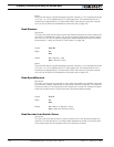
Switch Status
Returns a 4 bit number (4 least significant bits of the byte), each representing the state of
one of the limit switch when installed. The ?W command described at “Read Encoder
Limit Switch Status” on page 144 is a preferred method for reading this information
Speed or Distance 1 or 2
These two registers contain either the measured speed or the measured distance.
Whether speed or distance information is returned depends on the settings contained in
the Mode register described at. This information is returned using the ?p query (see
“Query Analog Inputs” on page 94)
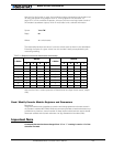
Counter Read/Write Mailbox
Since the counters are 32 bits wide and accesses are 8 bit wide, it would normally take
four separate accesses to fully read or write any of the counters. If the motors are running
and the counter is changing in-between these accesses, inaccurate data will be either read
or written. Therefore a two step process is implemented for accessing the encoder’s
counters: for loading a new value in the counter, the value must first be loaded in the mail-
box. It is then transferred in a single step using a command. When reading a counter, a
read command is sent to the encoder module who then copies the counter value into the
mailbox. The mailbox system can be used in the same way for reading and writing the des-
tination register.
Practically reading a counter is done by a single command described in “Read Encoder
Counter” on page 142. This command will perform the steps above and output the
selected counter value.
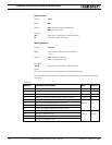
Writing a user-defined value into a counter or destination register requires that the value be
loaded in the mailbox using the steps defined in “Read / Modify Encoder Module Registers
and Parameters” on page 145, and then the issuance of one of the commands described
in “Set/Reset Encoder Counters and Destination Registers” on page 143.
Counter 1 and 2
These two 32-bit (4-bytes) registers are the actual counters. As discussed above, they
should not be accessed directly as their value may be changing in-between the four
accesses needed to read or write a complete 32-bit counter.
Destination Register 1 and 2
These two 32-bit (4-bytes) registers are used to store the desired destination when the
controller is used in position mode. These registers should always be set using the mailbox
mechanism described above. See “Using the Encoder to Track Position” on page 140 for a
complete description of the position mode.
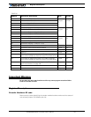
Distance 1 and 2
These registers contain a signed 8-bit value (-127 to +127) that represents the distance
between the current counter position and the desired destination. This number is com-
puted using a formula described in section “Using the Encoder to Track Position” on
page 140.