


AX2500/2850 Motor Controller User’s Manual 71
Connector I/O Pin Assignment (R/C Mode)
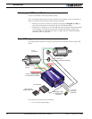
• at least one motor
• optional 12V backup power supply for the controller
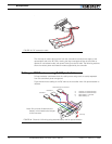
• R/C radio
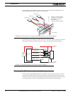
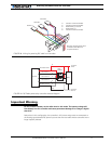
See “Connecting Power and Motors to the Controller” on page 25. The connection to the
R/C radio is further detailed n this chapter.
The optional connections are the following:
• optional 12V backup power supply for the controller
• the speed or position sensors required for closed loop speed or position operation
• 1 or 2 electrical accessory (valve, weapon, solenoid, ...)
• thermistor for motor temperature monitoring
• gravity actuated switch for detecting inverted operation
• manual switch for emergency stop
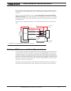
• the R/C receiver’s battery may also be omitted by using the power output available
on the controller’s connector
See “Connecting Sensors and Actuators to Input/Outputs” on page 49.
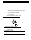
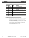
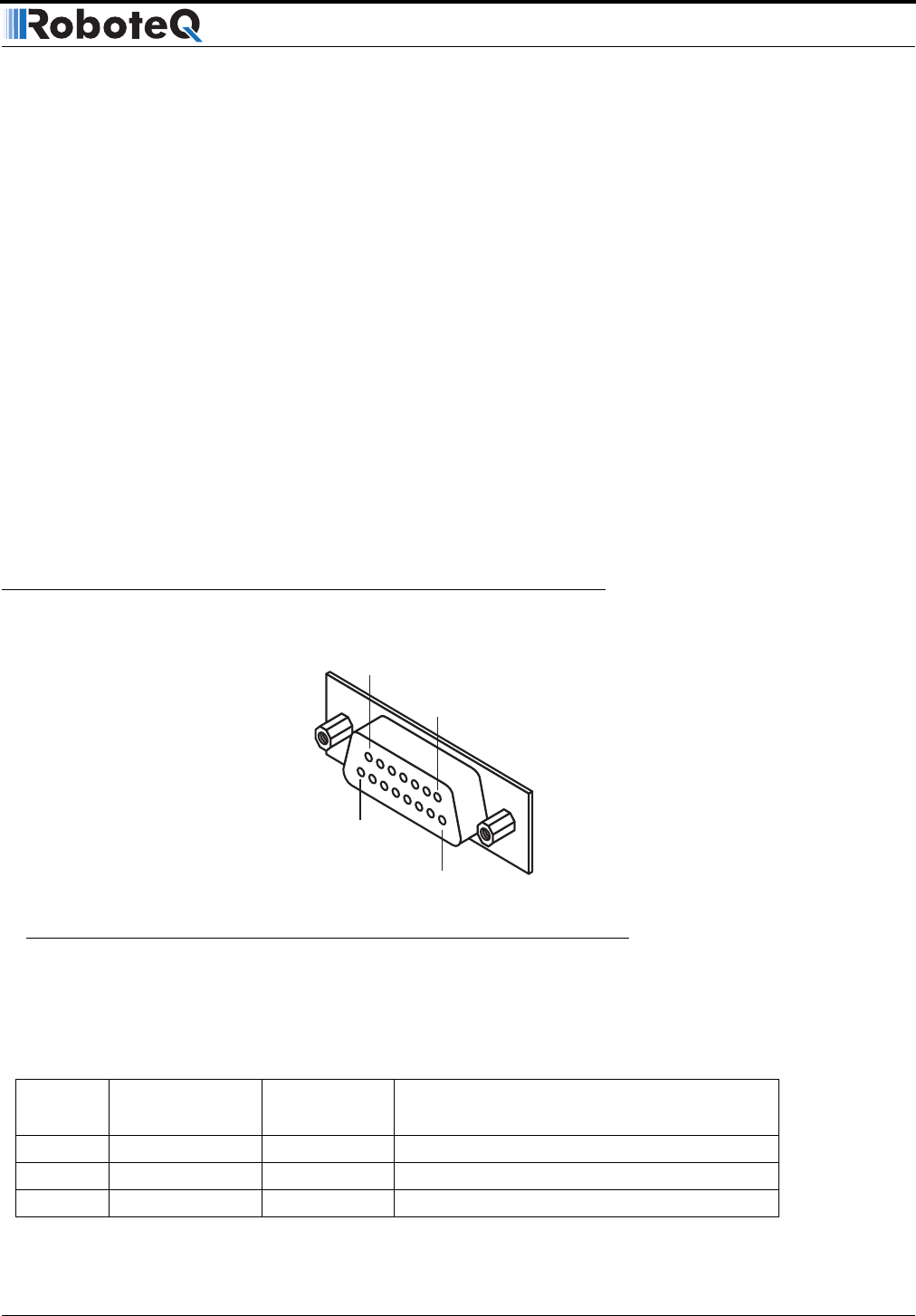
Connector I/O Pin Assignment (R/C Mode)
When used in R/C mode, the pins on the controller’s DB15 connector are mapped as
described in the table below
TABLE 15. Connector pin-out in R/C mode
Pin
Number Signal
Input or
Output Description
1 Output C Output 2A Accessory Output C (same as pin 9)
2 RS232 Out Output Optional. Used for Data Logging
3 R/C Channel 1 Input Channel 1 input pulse (isolated)
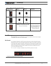
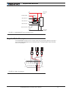
Pin1
8
15
9
FIGURE 40. Pin locations on the controller’s 15-pin connector