R/C Operation
80 AX2500/2850 Motor Controller User’s Manual Version 1.7. February 1, 2005
Another important consideration is the R/C receiver’s ability to operate in an electrically
noisy environment: the AX2500/2850 switches high current at very high frequencies. Such
transients along long battery and motor wires will generate radio frequency noise that may
interfere with the R/C radio signal. The effects may be reduced remote control range and/
or induced errors in the command pulse resulting in jerky motor operation.
A higher quality PCM R/C transmitter/radio is recommended for all professional applica-
tions, as these are more immune to noise and interference.
While a more noise-immune radio system is always desirable, it is also recommended to
layout the wiring, the controller, radio and antenna so that as little electrical noise is gener-
ated in the first place. Section “Electrical Noise Reduction Techniques” on page 31 pro-
vides a few suggestions for reducing the amount of electrical noise generated in your
robot.
Joystick Deadband Programming
In order to avoid undesired motor activity while the joysticks are centered, the AX2500/
2850 supports a programmable deadband feature. A small deadband is set into the control-
ler by default at the factory. This deadband can be stretched, reduced or eliminated by
changing the “d” parameter using one of the three methods described in the chapter
“Configuring the Controller using the Switches” on page 153. The AX2500/2850 has 8 pre-
set deadband values coded 0 to 7. The value 0 disables the deadband. Other values select
a deadband according to the table below. The deadband value applies equally to both joy-
sticks
The deadband is measured as a percentage of total normal joystick travel. For example, a
16% deadband means that the first 16% of joystick motion in either direction will have no
effect on the motors. If the joystick is recalibrated to operate using a shorter travel (see
“Joystick Calibration” on page 81), the percent value in the table will not be as accurate.
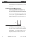
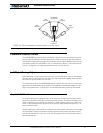
Note that the deadband only affects the start position at which the joystick begins to take
effect. The motor will still reach 100% when the joystick is at its full position. An exagger-
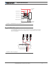
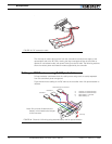
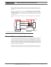
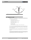
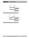
ated illustration of the effect of the deadband on the joystick action is shown in the
Figure 52 below.
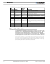
TABLE 16. Selectable deadband values
Deadband Parameter Value Deadband as Percent of full Joystick Travel
d = 0 No deadband
d = 1 8%
d = 2 16% - default value
d = 3 24%
d = 4 32%
d = 5 40%
d = 6 46%
d =7 54%


