Installing, Connecting and Using the Encoder Mod-
136 AX2500/2850 Motor Controller User’s Manual Version 1.7. February 1, 2005
Motor - Encoder Polarity Matching
When using the Encoder module for closed loop speed control, it is imperative that when
the motor is turning in the forward direction, the counter increments its value, and that a
positive speed value is measured.
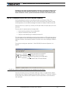
Using the PC utility, it is possible to exercise the motors and view the encoder readings.
See “Encoder Testing and Setting Using the PC Utility” on page 150.
If the Encoder counts backwards when the motor moves forward, you may correct this by
either:
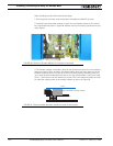
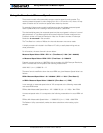
1- Swap Channel A and Channel B on the encoder connector. This will cause the encoder
module to reverse the count direction
2- Swap the leads on the motor. This will cause the motor to rotate in the opposite direc-
tion.
Voltage Levels, Thresholds and Limit Switches
The encoder module’s input uses a comparator to reshape the encoder’s output signal. If
the signal is below a programmable threshold level, then it is considered as a 0. If above, it
is considered at 1. The output of this comparator feeds the quadrature detector and
counters.
On the 2850 family of controllers, the threshold voltage may be changed under software
control to any value between 0 and 5V to meet unusual encoder specifications. By default,
the threshold level is 2.5V.
Another set of comparators on the same input signals detect pulses that above and below
a fixed 0.5V threshold. Using a special circuitry for creating multi-level signaling (see next
section below), the output of these comparators serves to detect the status of optional
limit switches.
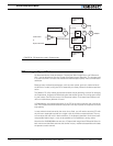
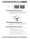
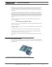
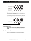
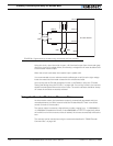
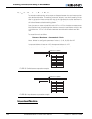
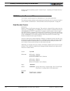
Figure 85 and Figure 84 show the conditioned signals as seen by the encoder.
In Figure 85, the encoders are connected directly to the Channel A and B inputs. In this
case, because the encoder’s 0 level is below 0.5V, it will cause a Switch Detection condi-
tion which should be ignored.
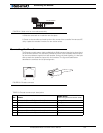
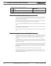
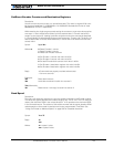
7 Ground Brown/White
85V Out Brown
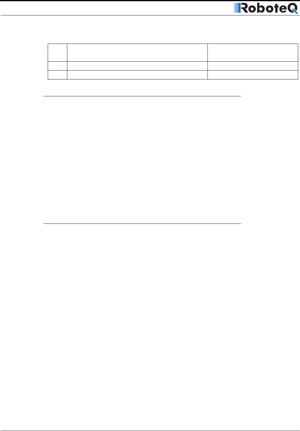
TABLE 23. Encoder connector pin descriptions
Pin Name
Cable Color
(when using standard network cable)


