


AX2500/2850 Motor Controller User’s Manual 149
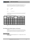
Counter Read Data Format
Speed 1 and 2
These registers contain a signed 8-bit value (-127 to +127) that represents the motor speed
relative to a maximum speed, which in turn depends on the number of encoder counts and
time base settings as described in “Using the Encoder to Measure Speed” on page 139.
Time Base 1 and 2
These registers contain the timing information for measuring the speed. See “Using the
Encoder Module to Measure Distance” on page 138 for a detailed description.
Encoder Threshold
This register contains a value that is used to detect a logic level 1 vs. a 0 at any of the 4
encoder input lines. Voltage threshold is computed as follows:
Voltage Threshold = 5V * Register Value / 255
See “Voltage Levels, Thresholds and Limit Switches” on page 136 for a detailed descrip-
tion.
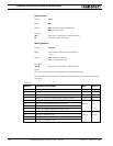
Counter Read Data Format
When receiving a counter read query, the encoder module will output the value of its 32-bit
counter. If all 32-bit are sent, this would require 8 ASCII digits to represent the value.
A 32-bit counter can store over 2 billion counts in each direction. Practically, it will be rare
that counts will be that large and therefore only a partial number of the counter’s bits will
be significant at any given time.
In order to create a more efficient data stream on the controller’s serial port, a simple com-
pression technique is implemented. The scheme eliminates all of the counter’s most signif-
icant bits if they are at 0 (for a positive count number) or F (for a negative count number).
For example, if the counter value is Hex 00000015, the value 15 will be returned after a
counter query.
For negative numbers, a count value of -5 (which is FFFFFFFB in hex), the response to the
query will be B.
To distinguish between positive and negative numbers, the Encoder module will insert a 0
ahead of any number string starting with a digit value higher than 7 (i.e. 8 to F) to signify
that the number is positive. For negative numbers, the Encoder module will insert an F
ahead of any number string starting with a digit value lower than 8 (i.e. 0 to 7). The table
below shows examples of this scheme as applied to various counter values
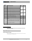
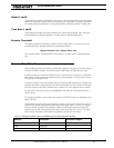
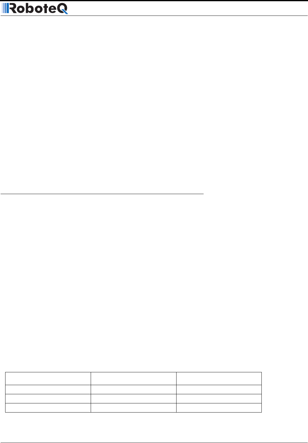
TABLE 26. Example counter values and RS232 output using reduction scheme
Decimal 32-bit Hex Controller Output
+5 00000005 5
+250 000000FA 0FA
-6 FFFFFFFA A