


AX2500/2850 Motor Controller User’s Manual 55
Connecting Switches or Devices to Input E
This output is not available on the AX2850 or on the AX2550 with the Encoder Mod-
ule installed.
Connecting Switches or Devices to Input E
Input E is a general purpose, digital input. This input is only active when in the RS232 and
Analog modes. In R/C mode, this line is used as the radio channel 3 input.
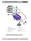
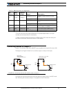
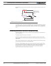
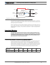
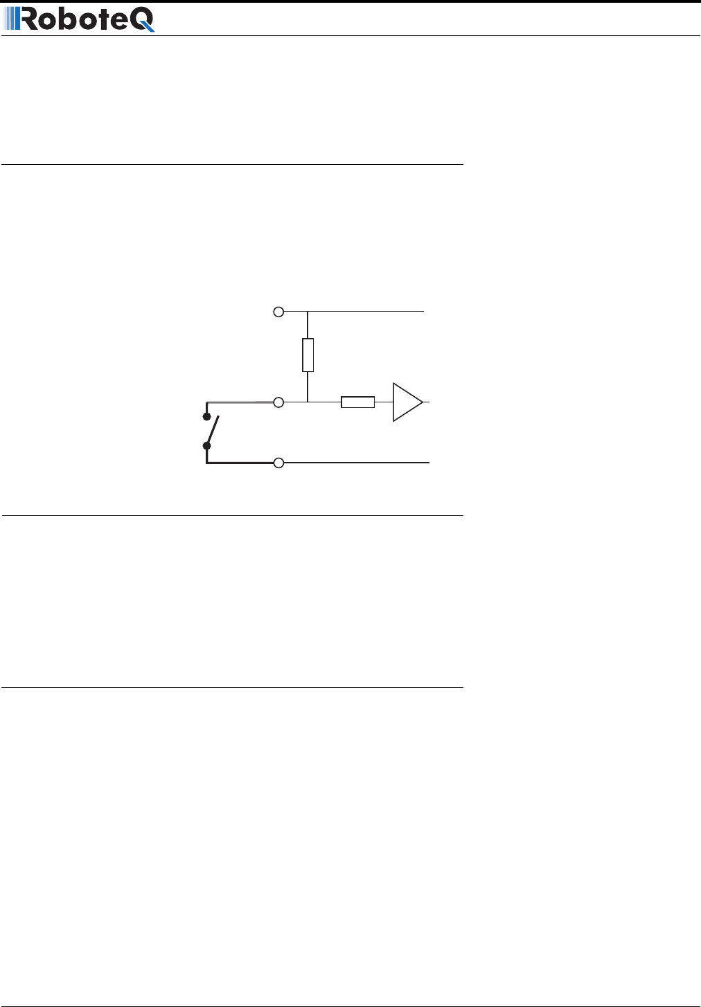
Input E is a high impedance input with a pull-up resistor built into the controller. Therefore
it will report an On state if unconnected, and a simple switch as shown on Figure 25 is nec-
essary to activate it.
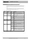
The status of Input E can be read in the RS232 mode with the ?i command string. The con-
troller will respond with three sets of 2 digit numbers. The status of Input E is contained in
the first set of numbers and may be 00 to indicate an Off state, or 01 to indicate an On
state.
This input is not available on the AX2850 or on the AX2550 with the Encoder Module
installed.
Connecting Switches or Devices to Input F
Input F is a general purpose digital input. This input is only active when in the RS232 mode.
In R/C mode, this line is used as the radio channel 2 input.
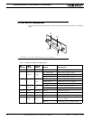
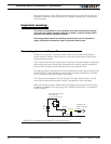
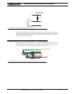
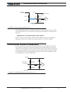
Input F is an opto-coupled input and requires the opto coupler buffer to be powered for it to
work. Figure 26 below shows how to wire the buffer’s power inputs (+5V In, GND In).
Seen from the outside, Input F is similar to input E, but with a lower impedance of
10kOhm. If left unconnected, this input will report an Off state. As a result, this input may
10kOhm
+5V Out 14
10kOhm
AX2500 Internal
Buffer and Resistors
Input E 8
Ground 5
FIGURE 25. Switch wirings to Input E