


AX2500/2850 Motor Controller User’s Manual 117
Potentiometer wiring
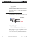
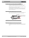
The mechanical coupling between the motor and the sensor must be as tight as possible.
If the gear box is loose, the positioning will not be accurate and will be unstable, potentially
causing the motor to oscillate.
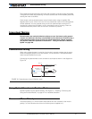
Some sensor, such as potentiometers, have a limited rotation range of typically 270
degrees (3/4 of a turn), which will in turn limit the mechanical motion of the motor/potenti-
ometer assembly. You may consider using a multi-turn potentiometer as long as it is
mounted in a manner that will allow it to turn throughout much of its range, when the
mechanical assembly travels from the minimum to maximum position.
Important Notice:
Potentiometers are mechanical devices subject to wear. Use better quality potenti-
ometers and make sure that they are protected from the elements. Consider using a
solid state hall position sensor in the most critical applications. Optical encoders
may also be used when operated as discussed in “Using the Encoder to Measure
Speed” on page 139.
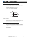
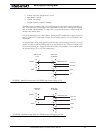
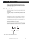
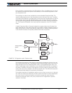
Potentiometer wiring
When using a potentiometer, it must be wired so that it creates a voltage that is propor-
tional to its angular position: 0V at one extreme, +5V at the other. A 10K potentiometer
value is recommended for this use.
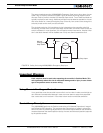
Connecting the potentiometer to the controller is as simple as shown in the diagram on
Figure 70.
Using Optical Encoders in Position Mode
Optical Encoders require special handling. See Figure 12, “Installing, Connecting and
Using the Encoder Module,” on page 131 for a detailed discussion.
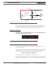
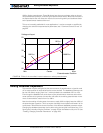
Sensor and Motor Polarity
The sensor polarity (i.e. which rotation end produces 0 or 5V) is related to the motor’s
polarity (i.e. which direction the motor turns when power is applied to it).
47kOhm
10kOhm
47kOhm
10kOhm
AX2500 Internal Resistors
and Converter
Input Pos 1 11
or Pos 2 10
+5V 14
Ground 5
A/D
FIGURE 70. Potentiometer wiring in Position mode