


Serial (RS-232) Controls and Operation
88 AX2500/2850 Motor Controller User’s Manual Version 1.7. February 1, 2005
Connector I/O Pin Assignment (RS232 Mode)
When used in the RS232 mode, the pins on the controller’s DB15 connector are mapped
as described in the table below
TABLE 17. DB15 Connector pin assignment in RS232 mode
Pin
Number Signal
Input or
Output Description
1 Output C Output 2Amp Accessory Output C (same as pin 9)
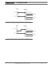
2 Data Out Output RS232 data output from the controller to the PC
3 Data In Input RS232 data input to the controller from the PC
4 Input F Input Accessory Input F
5 Ground Out Power Output Controller ground (-)
6 Ground In Power Input Must be wired to pin 13 or pin 5
7 +5V In Power Input Must be wired to pin 14
8 Input E Input Accessory input E - (Not available on AX2850)
9 Output C Output 2Amp Accessory Output C (same as pin 1)
10 Speed/Pos/T 2 Analog in Channel 2 speed, position or temp feedback
11 Speed/Pos/T 1 Analog in Channel 1 speed, position or temp feedback
12 Output D Output Low Current Accessory Output D - (Not available
on AX2850)
13 Ground Out Power Controller ground (-)
14 +5V Out Power Output +5V Power Output (100mA max.)
15 Switch Input Input Emergency Stop or Invert Switch input
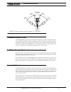
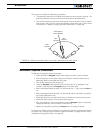
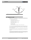
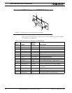
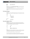
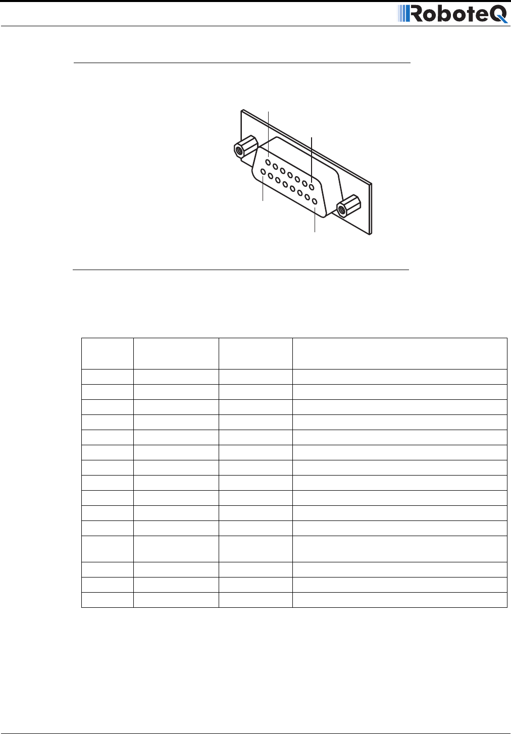
Pin1
8
15
9
FIGURE 1. Pin locations on the controller’s 15-pin connector