


AX2500/2850 Motor Controller User’s Manual 119
Adding Safety Limit Switches
Never apply a command that is lower than the sensor’s minimum output value, or
higher than the sensor’s maximum output value as the motor would turn forever try-
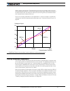
ing to reach a position it can’t. For example if the max position of a potentiometer is
4.5V, which is a position value of 114, a destination command of 115 cannot be
reached and the motor will not stop.
Adding Safety Limit Switches
The Position mode depends on the position sensor providing accurate position information.
If the potentiometer is damaged or one of its wire is cut, the motors may spin continuously
in an attempt to reach a fictitious position. In many applications, this may lead to serious
mechanical damage.
To limit the risk of such breakage, it is recommended to add limit switches that will cause
the motors to stop if unsafe positions have been reached, independently of the potentiom-
eter reading.
Two simple and low cost methods are proposed to implement safety limit switches:
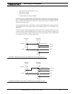
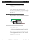
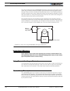
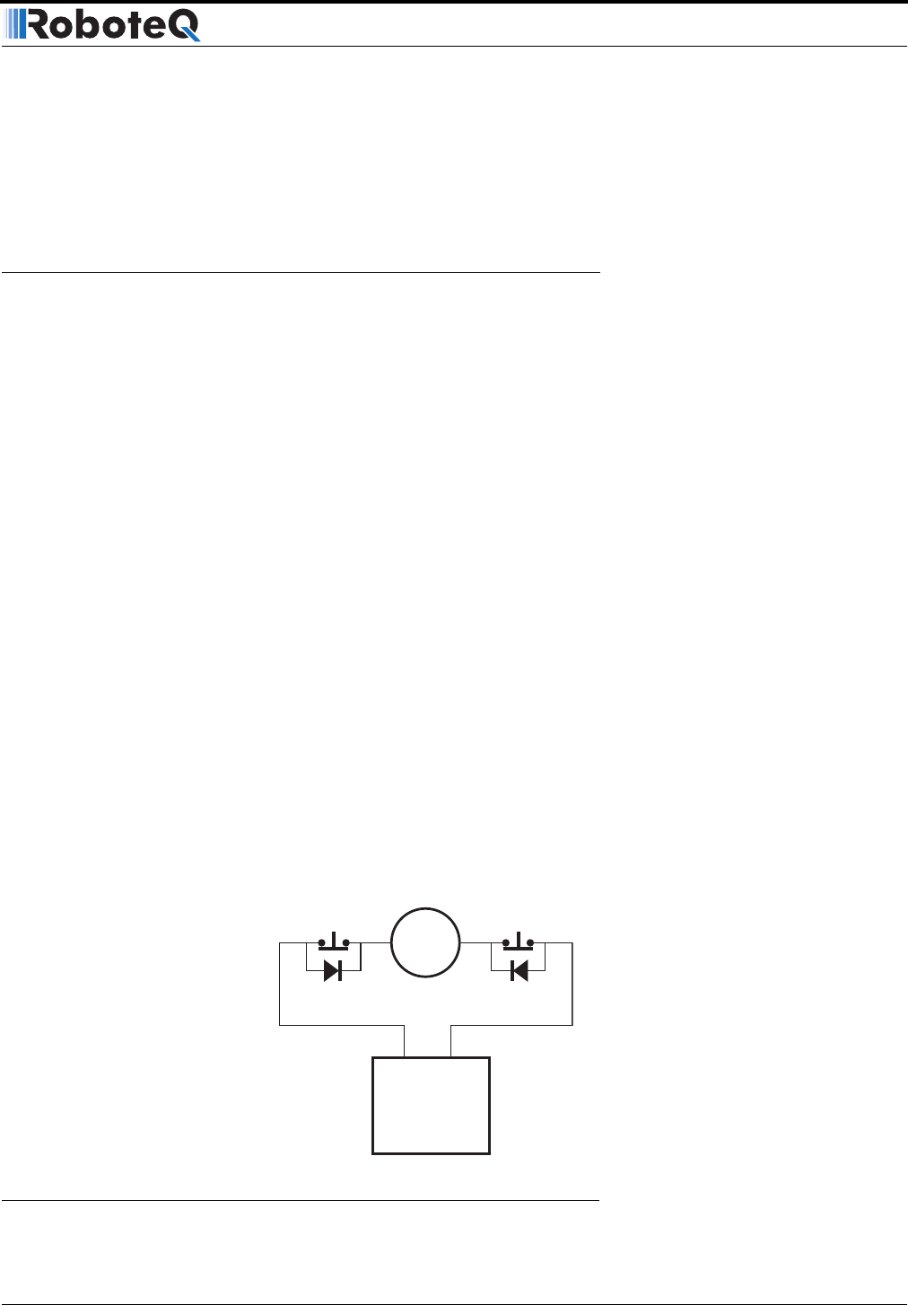
The first, shown in Figure 71, uses Normally Closed limit switches in series on each of the
motor terminals. As the motor reaches one of the switches, the lever is pressed, cutting
the power to the motor. The diode in parallel with the switch allows the current to flow in
the reverse position so that the motor may be restarted and moved away from that limit.
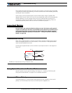
The diode polarity depends on your particular wiring and motor orientation. If the diode is
mounted backwards, the motor will not stop once the limit switch lever is pressed. If this is
the case, reverse the diode polarity.
The diodes may be eliminated, but then it will not be possible for the controller to move the
motor once either of the limit switches has been triggered.
The main benefit of this technique is its total independence on the controller’s electronics
and its ability to work in practically all circumstances. Its main limitation is that the switch
and diode must be capable of handling the current that flows through the motor. Note that
the current will flow though the diode only for the short time needed for the motor to move
away from the limit switches.
Motor
SW1 SW2
AX2550
FIGURE 71. Safety limit switches interrupting power to motors