


R/C Operation
74 AX2500/2850 Motor Controller User’s Manual Version 1.7. February 1, 2005
.
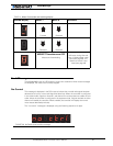
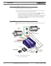
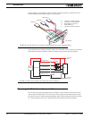
The wire loop is used to bring power from the controller’s internal power supply to the
optocouplers and to the RC radio. Leaving the loop untouched causes the controller to
operate in non-isolated mode, with power flowing into the RC radio. The following sections
show the various power and isolation modes supported by the controller.
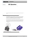
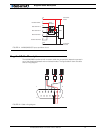
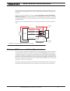
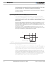
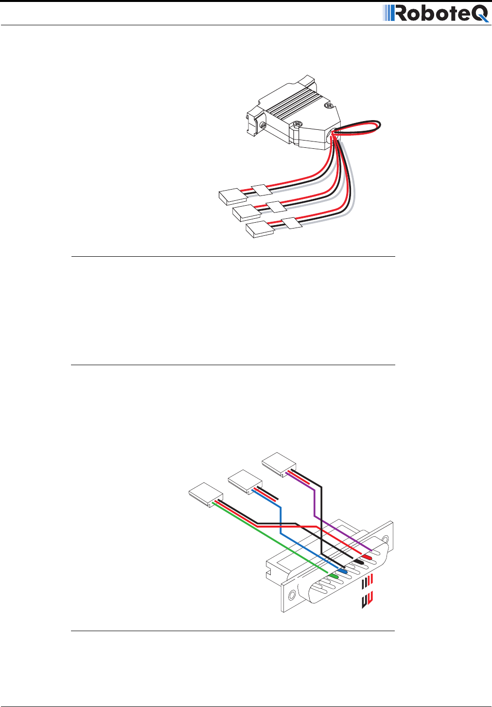
Cabling to R/C Receiver using Full Opto-Isolation
Full opto-isolation is achieved when the radio’s power and ground are totally separated
from the controller’s power and ground.
Figure 44 shows the cabling of the R/C radio to the controller when full optical isolation is
required.
3
2
1
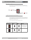
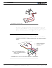
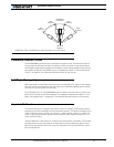
FIGURE 43. RC connection cable
8
9
15
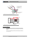
Pin 1
Channel 1
Channel 2
3: Channel 1 Command Pulses
4: Channel 2 Command Pulses
6: Radio battery (-) Ground
7: Radio battery (+)
Channel 3: Do not connect
Cut loop
Note: Only one set of black and red
(battery) wires needs to be brought
to the connector.
FIGURE 44. Channel 1 & 2 wiring using external battery and full optical isolation