AX2500/2850 Motor Controller User’s Manual 39
Temperature-Based Current Limitation
You can select one of 7 current limit settings based on your robot’s component capabilities
(motors, battery, wiring), up to the controller’s own limit. The available current limit values
are shown in the table below.
The controller will assume that any consumption above the safe continuous amps value
will cause more heat to be generated than can be safely dissipated. The controller will
keep an internal total of the estimated heat balance and will begin gradually reducing the
output power when a maximum threshold has been reached. The higher the current is over
the Continuous Safe Amps limit, the quicker it will reach the maximum threshold.
In practice, assuming the maximum Amps limit setting (120A), this means that the control-
ler will allow up to 1 minute of operation at 100A or 15 seconds at 120A. When the control-
ler runs below the Continuous Safe Amps limit, the controller will assume that it is cooling
off and will allow for higher amp consumption at a later time. In practical robot maneuver-
ing situations where stop and go is very common, the controller will be capable of deliver-
ing the maximum Momentary High Amps whenever it is needed.
Temperature-Based Current Limitation
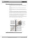
The AX2500/2850 also features active current limitation with a SmartAmps control algo-
rithm. On the AX2500/2850, this current limiting is based on the actual measured tempera-
ture of the heat sink, near the mounting point of the Power MOSFET transistors inside the
controller. While the temperature is below 60oC, the controller will deliver up to 120A Con-
tinuous Amps. For every degree of temperature rise above that threshold value, the limit is
reduced from this absolute maximum amount. Furthermore you can select one of 7 cur-
rent limit settings based on your robot’s component capabilities (motors, battery, wiring),
up to the controller’s own limit. The current limit that is applied at any given time is the
lesser value of your selected value, the computed limit using the SmartAmps algorithm
and the maximum Amps the controller is allowed to deliver at its current temperature
point. This capability ensures that the controller will be able to work safely with practically
all motor types and will adjust itself automatically for the various load and environmental
conditions. The time it takes for the heat sink’s temperature to rise depends on the current
output, ambient temperature, and available air flow (natural or forced).
Note that the measured temperature is on the inside of the heat sink and will rise and fall
faster than the outside surface.
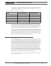
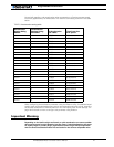
TABLE 7. Continuous vs. Extended Amp limits table
Setting Continuous High Amps Extended Safe Amps
0 30A 30A
1 45A 45A
2 60A 60A
3 75A 75A
4 90A 80A
5 105A 80A
6 120A 80A


