


R/C Operation
72 AX2500/2850 Motor Controller User’s Manual Version 1.7. February 1, 2005
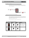
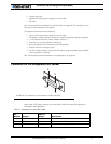
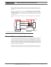
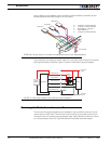
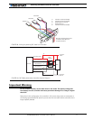
R/C Input Circuit Description
The AX2500/2850 includes an optical isolation barrier on the Channel 1 and Channel 2 R/C
radio inputs. Figure 41 shows an electrical representation of the R/C input circuit. The right
side is powered from the controller’s batteries. The R/C signals 1 and 2 activate a LED
whose light then triggers the photo transistors on the microcontroller side. The left side of
the opto isolators include an amplifier and thus need to be powered separately. Notice that
channel 3 is optional and not opto-isolated.
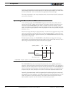
Optical isolation is designed to protect the R/C radio from damage that may occur inside
the controller, and vice-versa. Additionally, the isolation barrier will help prevent some of
the electrical “noise” generated inside the controller by the Microcontroller and the high
power switching from reaching and interfering with the radio.
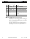
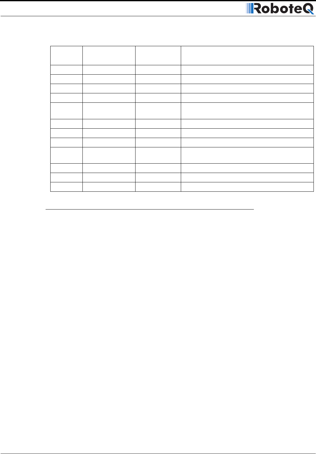
4 R/C Channel 2 Input Channel 1 input pulse (isolated)
5 Ground Power Controller ground (-)
6 R/C - Power Input R/C Battery input - (isolated)
7 R/C + Power Input R/C Battery input + (isolated)
8 R/C Channel 3 Input Channel 3 input for On/Off accessories - Not avail-
able on AX2850.
9 Output C Output 2A Accessory Output C (same as pin 1)
10 Speed/Pos/T 2 Analog in Channel 2 speed, position or temp feedback
11 Speed/Pos/T 1 Analog in Channel 1 speed, position or temp feedback
12 Output D Output Low Current Accessory Output D - Not available
on AX2850.
13 Ground Power Controller ground (-)
14 +5V Power Output +5V Power Output (100mA max.)
15 Switch Input Input Emergency Stop or Invert Switch input
TABLE 15. Connector pin-out in R/C mode
Pin
Number Signal
Input or
Output Description