


AX2500/2850 Motor Controller User’s Manual 169
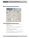
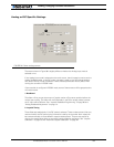
Running the Motors
The Power field displays the power level that is actually being applied to the motor. This
value is directly related to the motor command except during current limitation, in which
case the power level will be the one needed to keep the Amps within the limit. Note that
the display value is not sign and thus does not provide rotation direction information
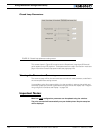
The Ana field contains the analog input value that is measured and reported by the control-
ler. When the controller is in the position mode, this field will display the position sensed
on the potentiometer. When in speed mode, this field displays the measured speed by the
tachometer.
In all other mode, this field will display the value at the analog input pin. A small button next
to this field will toggle the display caption, and conversion algorithm from raw analog, volts
or temperature.
Note that in order to measure and display external temperature or voltage, the proper
external components must be added to the controller. See “Connecting External Ther-
mistor to Analog Inputs” on page 59 and “Using the Analog Inputs to Monitor External
Voltages” on page 60.
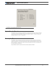
The Enc field contains the speed or position measured by the Optical Encoder if enabled.
The Te m p field displays the heat sink temperature for each channel
The Bat Volt field displays the main battery’s voltage (voltage applied to the thick red
wires).
The Ctrler Volt field displays the controller’s internal regulated 12V voltage.
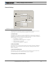
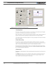
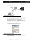
4- Real-Time Strip Chart Recorder
This chart will plot the actual Amps consumption and other parameters as measured from
the controller. When active, the chart will show measurement during the last five seconds.
The two handles at the bottom of the chart are zoom in or out the history sample that is to
be displayed on the chart. Using these handles it is possible to go back and examine any
event up to 5 minutes into the past. This feature is extremely useful during development
and test of the robotic vehicle.
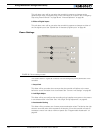
5- Transmit and Receive Data
These two fields show the data being exchanged between the PC and the controller. While
these fields are updated too fast to be read by a person, they can be used to verify that a
dialog is indeed taking place between the two units.
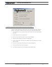
After the Start button is pressed, the Tx field will show a continuous string of commands
and queries sent to the controller.
The Rx field will display the responses sent by the controller. If this field remains blank or is
not changing even though the Tx field shows that data is being sent, then the controller is
Off or possibly defective. Try resetting the controller and pressing the Run/Stop button.
6- Input Status and Output Setting
This section includes two check boxes and three color squares. The check marks are used
to activate either of the controller’s two outputs. The color blocks reflect the status of the