


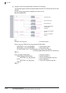
5.3 Serial Communication
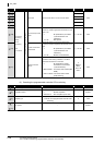
5.3.11 CSET instruction (programmable controller CPU monitor)
5-97
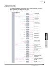
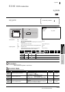
ZP_CSET
5
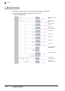
MODULE DEDICATED
INSTRUCTION
ZP_CSET
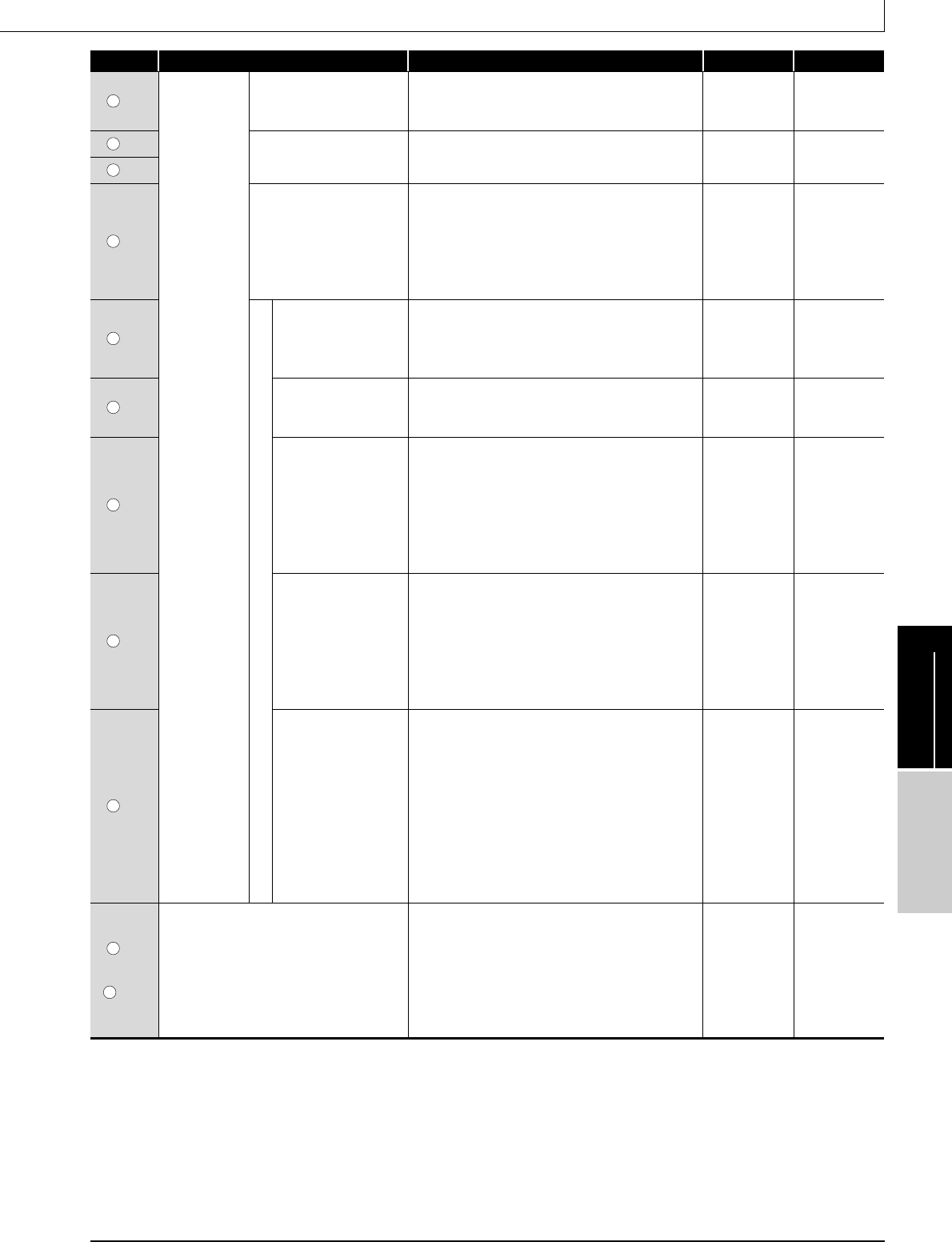
[13]
Programmable
controller CPU
monitoring
setting
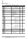
1st
* 1st block
Device code
Specify the code of the device to be monitored.
0 : No device monitored
Other than 0 : Device code
90
H to CCH
(Device code)
User
[14]
Monitoring start device
Specify the start number of the monitoring device in
this block.
0 or more
User
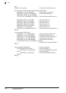
[15]
[16]
Number of registered points
Specify the number of registered points (read points)
of this block.
0 : No device monitored
1 or more : Number of registered points
* For a bit device, specify the number of points in units
of words.
0, 1 or more
User
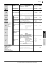
[17]
Condition agreement transmission
Monitoring condition
Specify the monitoring condition of this block.
0 : No specification (at constant
cycle transmission)
1 or more : Monitoring condition
0 to 65535
User
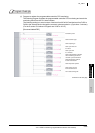
[18]
Monitoring condition
value
Specify the monitoring condition value for this block.
0 or more: Monitoring condition
* Specify '0' at constant cycle transmission.
0 to 000AH,
0101
H to
010A
H
User
[19]
User frame output start
pointer
Specify the start pointer of the table to which the user
frame number for condition agreement transmission
for this block is set.
0 : No specification (at constant
cycle transmission and
notification)
1 to 100 : Start pointer
0, 1 to 100
User
[20]
Number of user frame
transmissions
Specify the number of user frame transmissions
(outputs) for condition agreement transmission for this
block.
0 : No specification (at constant
cycle transmission and
notification)
1 to 100 : Number of transmissions
0, 1 to 100
User
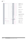
[21]
Modem connection
data No.
Specify the data number for modem function
connection when making notification in condition
agreement transmission for this block.
0 : No specification (at data
transmission and constant
cycle transmission)
BB8
H to BD5H : Connection data number (flash
ROM)
8001
H to 801FH: Connection data number
(buffer memory)
0,
BB8
H to
BD5
H,
8001
H to
801F
H
User
[22]
to
[102]
Programmable
controller CPU
monitoring
setting
2nd to 10th
* 2nd to 10th block
The same item arrangement as the first
programmable controller CPU monitoring setting item.
– User
Device Item Setting data Setting range Setting side
s2
s2
s2
s2
s2
s2
s2
s2
s2
s2
s2