


8-28
8.2 Counter Function Dedicated Instruction
8.2.10 ICPWM instruction
ICPWM1, ICPWM2
8.2.10 ICPWM instruction
ICPWM1, ICPWM2
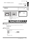
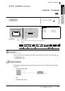
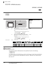
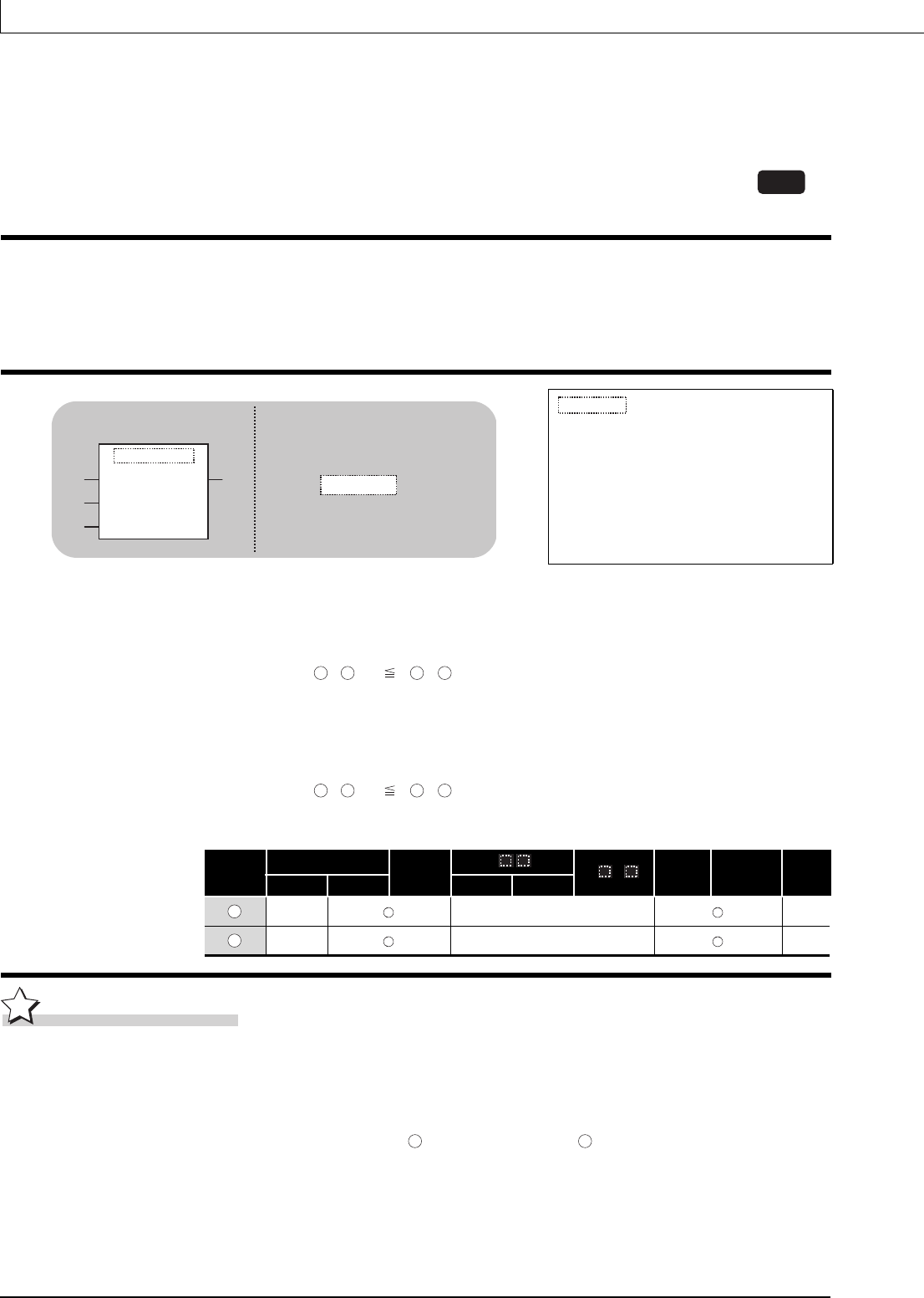
Function
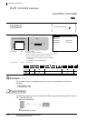
This instruction outputs a PWM waveform of the specified CH (refer to the following).
• ICPWM1: CH1
• ICPWM2: CH2
The PWM waveform with the ON time ( ) and the cycle time ( ) is output from the coincidence
output No.1 signal during the ICPWM instruction execution. The output of the PWM waveform
starts from OFF.
ICPWM1
ICPWM2
indicates any of the following
instructions.
ICPWM1
ICPWM2
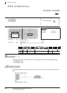
Input argument
EN:
Executing condition :Bit
s1:
PWM output ON time setting value (constant), or start number
of the device that stores the PWM output ON time setting
value
• Constant: Settings which is 0 or within the range of 10 to 10
7
(0.1µs) and ( ,
+1) ( , +1)
• Device: Within the range of specified device
:ANY32
s2:
PWM output cycle time setting value (constant), or start
number of the device that stores the PWM output cycle time
setting value
• Constant: Settings which is 0 or within the range of 50 to 10
7
(0.1µs) and ( ,
+1) ( , +1)
• Device: Within the range of specified device
:ANY32
Output argument
ENO:
Execution result :Bit
Setting
data
Internal device
R, ZR
J\
U\G
Zn Constant Others
Bit Word Bit Word
LCPU
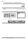
ST
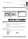
ICPWM1
EN ENO
s1
s2
ICPWM1
(EN, s1, s2);ENO:=
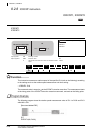
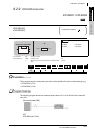
Structured ladder/FBD
s1
s1
s2
s2
s1
s1
s2
s2
s1
s2
s1
s2