


8.2 Counter Function Dedicated Instruction
8.2.2 ICRNGWR instruction
8-19
8
BUILT-IN I/O FUNCTION
INSTRUCTION
ICRNGWR1, ICRNGWR2
ICRNGWR1, ICRNGWR2
8.2.2 ICRNGWR instruction
ICRNGWR1, ICRNGWR2
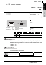
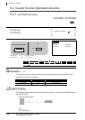
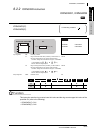
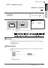
Function
This instruction sets the ring counter lower limit value and the ring counter upper limit value of the
specified CH (refer to the following).
• ICRNGWR1(P): CH1
• ICRNGWR2(P): CH2
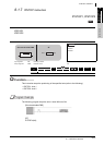
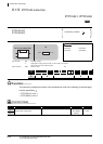
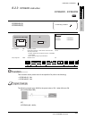
ICRNGWR1(P)
ICRNGWR2(P)
P: Executing condition
:
indicates any of the following
instructions.
ICRNGWR1 ICRNGWR1P
ICRNGWR2 ICRNGWR2P
Input argument
EN:
Executing condition :Bit
s1:
Ring counter lower limit value (constant), or start number of
the device that stores the ring counter lower limit value
• Constant: Settings which is within the range of -2147483648
to 2147483647 and ( ,
+1) ( , +1)
• Device: Within the range of specified device
:ANY32
s2:
Ring counter upper limit value (constant), or start number of
the device that stores the ring counter upper limit value
• Constant: Settings which is within the range of -2147483648
to 2147483647 and ( ,
+1) ( , +1)
• Device: Within the range of specified device
:ANY32
Output argument
ENO:
Execution result :Bit
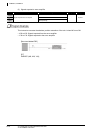
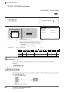
Setting
data
Internal device
R, ZR
J\
U\G
Zn Constant Others
Bit Word Bit Word
LCPU
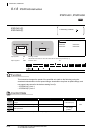
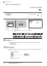
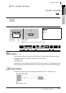
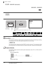
ST
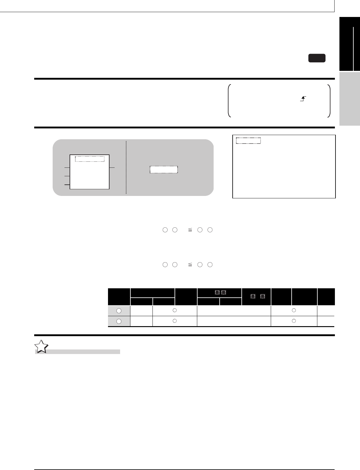
ICRNGWR1
EN ENO
s1
s2
ICRNGWR1
(EN, s1, s2);ENO:=
Structured ladder/FBD
s1 s1 s2 s2
s1
s1
s2
s2
s1
s2