


111
CHAPTER 8 FUNCTION
8
8.13 CC-Link IE Field Network Synchronous Communication Function
Ex.
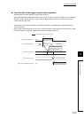
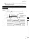
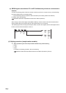
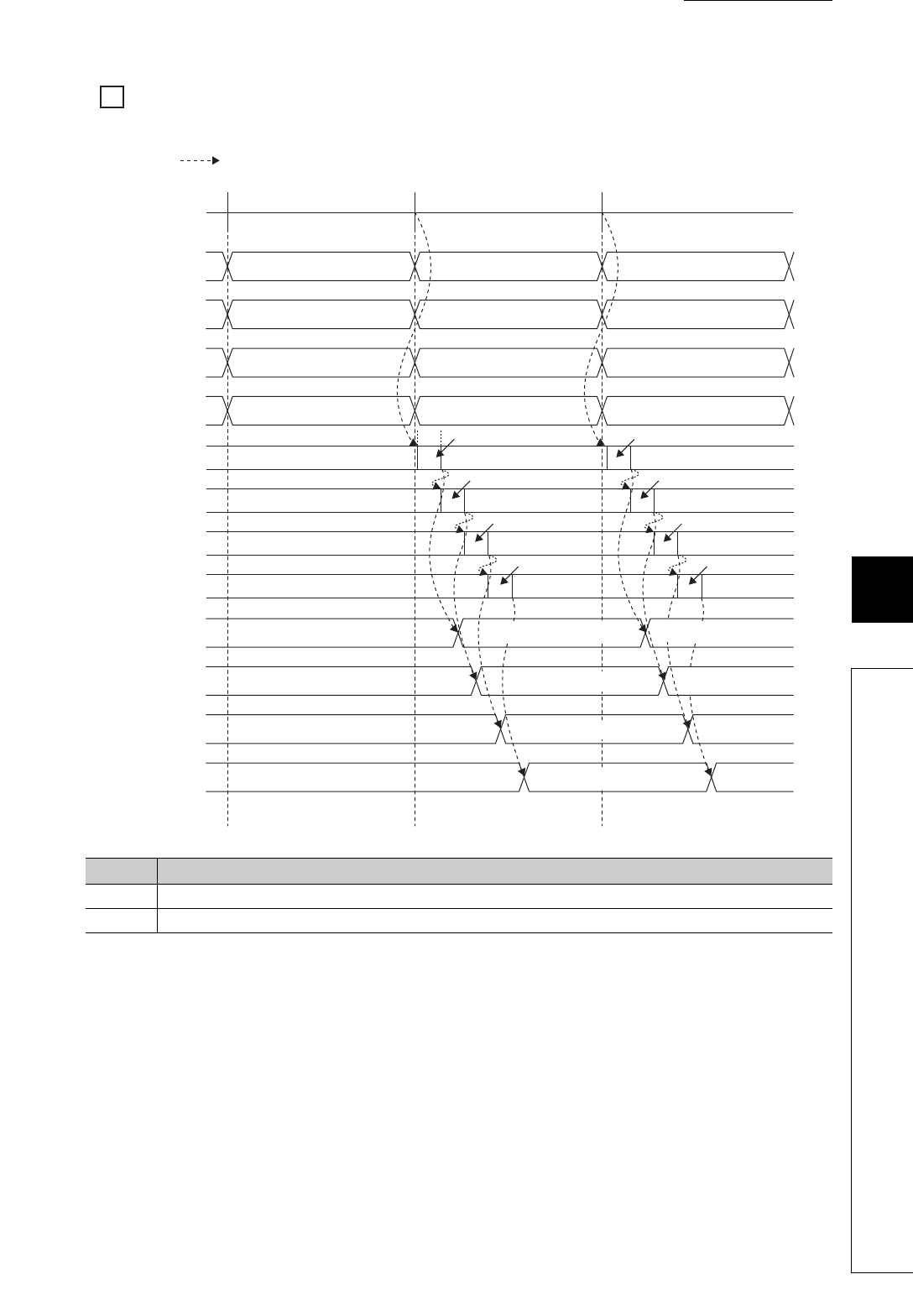
The following figure shows an example of the operation timing of when D/A conversion is enabled for all
channels.
No. Description
1) The D/A conversion is started when the operation of the simple motion module shifts to the next cycle.
2) The D/A conversion is performed for 100µs per channel, from CH1 to CH4.
1)
2)
100µs
2)
2)
Controlled by the D/A converter module
CH1 D/A conversion
CH2 D/A conversion
CH3 D/A conversion
CH4 D/A conversion
CH1 Digital value (first time) CH1 Digital value (second time) CH1 Digital value (third time)
CH2 Digital value (first time) CH2 Digital value (second time) CH2 Digital value (third time)
CH3 Digital value (first time) CH3 Digital value (second time) CH3 Digital value (third time)
CH4 Digital value (first time) CH4 Digital value (second time)
D/A conversion
CH4 Digital value (third time)
CH1 D/A conversion value
(first time)
CH1 D/A conversion value
(second time)
CH2 D/A conversion value
(first time)
CH2 D/A conversion value
(second time)
CH3 D/A conversion value
(first time)
CH3 D/A conversion
value (second time)
CH4 D/A conversion value
(first time)
CH4 D/A conversion
value (second time)
Operation cycle of the simple
motion module
CH1 Digital value
(RWw2)
CH2 Digital value
(RWw3)
CH3 Digital value
(RWw4)
CH4 Digital value
(RWw5)
CH1 Analog output value
CH2 Analog output value
CH3 Analog output value
CH4 Analog output value
D/A conversion
D/A conversion D/A conversion
D/A conversion D/A conversion
D/A conversion D/A conversion