


20
2)
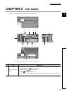
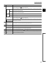
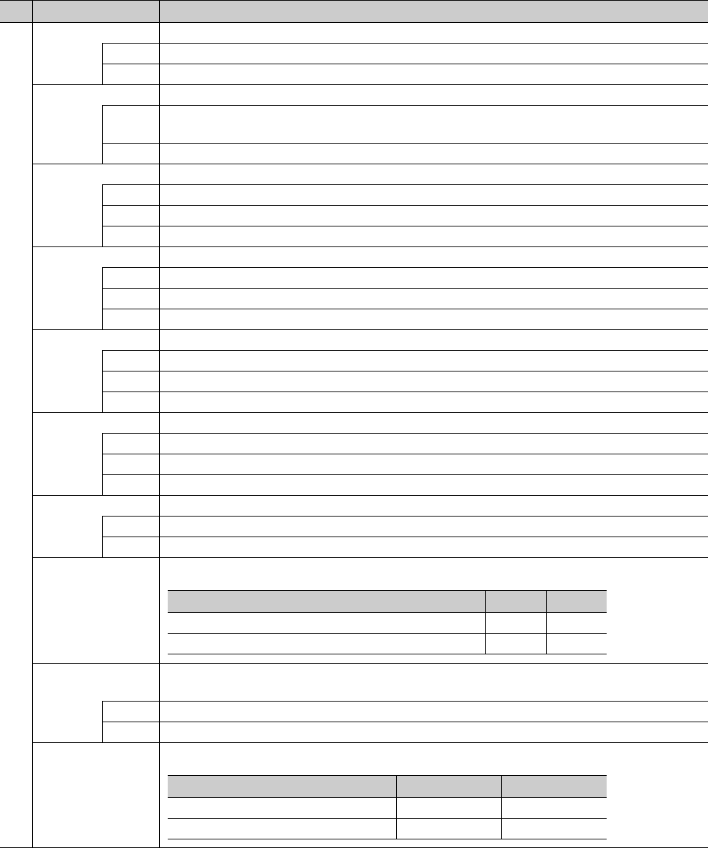
PW LED (green) Indicates the operating status of the D/A converter module.
ON Power supply ON
OFF Power supply OFF
RUN LED (green) Indicates the operating status of the D/A converter module.
ON
Operating normally.
Writing data to the nonvolatile memory in the offset/gain setting mode.
OFF A major error has occurred or in the offset/gain setting mode.
MODE LED (green) Indicates the mode of the D/A converter module.
ON In online mode.
Flashing In unit test mode.
OFF In offset/gain setting mode.
D LINK LED (green) Indicates the data link status of the D/A converter module.
ON Data link in operation. (cyclic transmission in progress)
Flashing Data link in operation. (cyclic transmission stopped)
OFF Data link not performed. (disconnected)
ERR. LED (red) Indicates the error status of the D/A converter module.
ON A moderate error or major error has occurred.
Flashing A warning has occurred.
OFF Operating normally.
ALM LED (red) Indicates the alert status of the D/A converter module.
ON Alert has occurred.
Flashing An out-of-range digital value error has occurred.
OFF Operating normally.
O/G LED (green) Indicates the module is in the offset/gain setting mode.
ON In offset/gain setting mode.
OFF In a mode other than the offset/gain setting mode.
V LED (green)
I LED (green)
Indicates the user range setting for the selected setting in the offset/gain setting mode.
CH1 to 4 LED
(green)
Indicates the channel for the selected setting in the offset/gain setting mode.
ON The channel of the number for which the LED turns on is the setting target.
OFF The channel of the number for which the LED turns off is not the setting target.
OFFSET LED (green),
GAIN LED (green)
Indicates whether the selected setting is offset or gain in the offset/gain setting mode.
No. Name Application
Setting target V LED I LED
User range setting 1 (voltage) ON OFF
User range setting 2 (current) OFF ON
Setting target OFFSET LED GAIN LED
Offset ON OFF
Gain OFF ON