


28
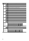
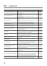
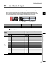
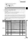
3.4 Function List
Item Description Reference
D/A conversion enable/disable function
Whether to enable or disable D/A conversion can be set for each channel.
Disabling the D/A conversion for unused channels reduces the
conversion cycles.
Page 80,
Section 8.3
D/A output enable/disable function
Whether to output the D/A conversion value or the offset value can be set
for each channel.
The conversion speed is constant, regardless of the output
enable/disable status.
Page 80,
Section 8.4
Range switching function
The output range can be selected for each channel from the following
ranges:
• Factory default range (4 to 20mA, 0 to 20mA, 1 to 5V, 0 to 5V, -10 to
10V)
• User range (user range setting 1, user range setting 2)
Page 81,
Section 8.5
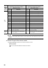
Offset/gain setting function This function compensates for errors in analog output values.
Page 75,
Section 7.3
Analog output HOLD/CLEAR function
Whether to hold or clear the output analog value can be set, according to
the CPU module operating status (RUN, STOP, or stop error).
Page 82,
Section 8.6
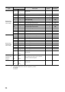
Cyclic data update watch function
The update intervals of cyclic data are monitored. The last output value is
held or cleared when the cyclic transmission stop status continues longer
than the set monitoring time.
Page 84,
Section 8.7
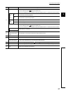
Scaling function
The D/A converter module scale-converts the digital value to the set
range of the scaling upper limit value and scaling lower limit value. The
programming for scale conversion can be reduced.
Page 85,
Section 8.8
Shift function
Using this function, the D/A converter module outputs the converted
digital value with the shifting set value added, in analog. Fine adjustment
can be performed easily when the system starts.
Page 91,
Section 8.9
Digital value range check function
An error is output when the digital value is out of the digital input range for
the output range.
Page 95,
Section 8.10
Alert output function
This function outputs alert when a digital value is in the range set in
advance.
Page 98,
Section 8.11
Trigger output function
Using this function, the D/A converter module performs the D/A
conversion at the timing of the execution of Trigger output request.
Trigger output request from the external device to the extension input
module can be used for the D/A conversion.
Page 101,
Section 8.12
CC-Link IE Field Network synchronous
communication function
With this function, the D/A converter module can perform D/A conversion
synchronized with the operation cycle of a simple motion module. This
enables the D/A converter module to operate at the same timing of other
slave stations on the same network.
Page 109,
Section 8.13
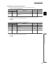
Error notification function
When a moderate error or major error occurs in the D/A converter
module, this function notifies the master station of the error with the
remote input signal.
Page 114,
Section 8.14
Function at the extension module installation
One extension I/O module can be connected to one D/A converter
module.
Remote input signals of the D/A converter module can be assigned to
remote output signals of the connected extension output module. In
addition, functions unique to the extension I/O module can be used.
Page 117,
Section 8.15
CC-Link IE Field Network diagnostic function
With this function, whether any network error occurs or not can be
checked through GX Works2 connected to the CPU module.
Page 121,
Section 8.16